I am a professional engineer and graduate from a reputed engineering university also have experience of working as an engineer in different famous industries. I am also a technical content writer my hobby is to explore new things and share with the world. Through this platform, I am also sharing my professional and technical knowledge to engineering students.
Follow me on:
Twitter and
Facebook.
Hello friends, I hope you all are doing great. In today’s tutorial, we will have a look at the Common Base Amplifier. The common base amplifier configuration is also called a grounded base is a basic single-stage amplifier configuration of BJT like a common collector and common emitter amplifier. This configuration is normally used in…
Hello friends, I hope you all are doing great. In today’s tutorial, we will have a look at the Introduction to Darlington Pair configuration and its applications. The Darlington pair also called Darlington transistor it was the first time created in 1953 by the United States electrical engineer Sidney Darlington due to that it called Darlington.…
Hello friends, I hope you all are doing great. In today’s tutorial, we will have a look at the Common collector Amplifier configuration and its applications. It is another category of BJT amplifier configuration in which input voltage is given at the base and output is taken at the emitter of the transistor. While collector…
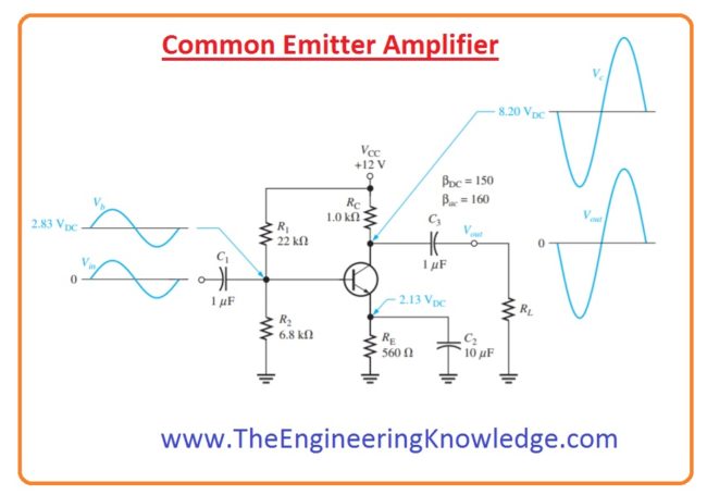
Hello friends, I hope you all are doing great. In today’s tutorial, we will have a look at Common Emitter Amplifier. In electronic engineering common emitter amplifier configuration is basic single-stage BJT amplifier technique it normally operate as voltage amplifier. In this configuration base of transistor work as input collector as output terminal and emitter…
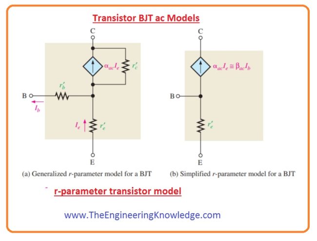
Hello friends, I hope you all are doing great. In today’s tutorial, we will have a look at Transistor or BJT AC Models.To analyze the working of a transistor in amplifier circuits it beneficial to denote the devices in the form of model circuits. The model circuit of transistor uses numerous interior parameters of transistor…
Hello friends, I hope you all are doing great. In today’s tutorial, we will have a look at Safety Tips for CoronaVirus (COVID-19).The word coronavirus is derived from the Latin word corona which means crown or halo. Coronavirus is a type of virus (A virus is a microscopic infectious agent that replicates in the living…
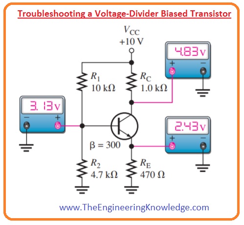
Hello friends, I hope you all are doing great. In today’s tutorial, we will have a look at Troubleshoot Faults in Transistor Bias Circuits. In a biased transistor, circuitry transistor can damage or resistance in bias circuitry can also damage. We will discuss numerous options in this post with the use of voltage divider biasing…
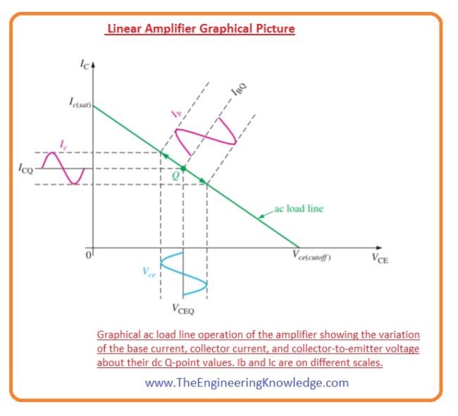
Hello friends, I hope you all are doing great. In today’s tutorial, we will have a look at Describe amplifier operation. The biasing process of a transistor is completely dc operation. The main function of biasing is to discuss a Q point due to which change in current and voltage can exit according to the…
Hello friends, I hope you all are doing great. In today’s tutorial, we will have a look at Transistor Biasing Method. In electronic devices and projects, transistors are very commonly used like amplifier and switch. For proper working transistors in this circuits specific amount of current and voltage is needed. The methods to provides these…
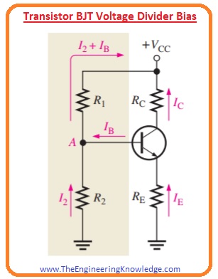
Hello friends, I hope you all are doing great. In today’s tutorial, we will have a look at Transistor BJT Voltage Divider Bias. The most common and normally used method for biasing a transistor is a voltage divider bias circuit. It consists of some resistances for division or voltages and distribution among resistance at a proper…


