 Hello friends, I hope you all are doing great. In today’s tutorial, we will have a look at Transistor or BJT AC Models.To analyze the working of a transistor in amplifier circuits it beneficial to denote the devices in the form of model circuits. The model circuit of transistor uses numerous interior parameters of transistor to define the operation.
The model of transistor we discuss in this post will be based on the resistance or r parameters. With those other parameters called h parameters will also be discussed with the detailed. So, let’s get started with the Transistor or BJT AC Models.
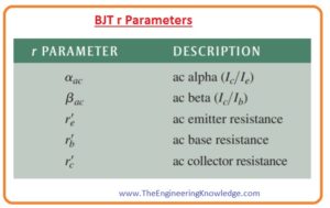
BJT r Parameters
- There are main 5 r parameters of bipolar junction usually used as shown in the below figure.
- The italic lowercase letter r with a prime identify the interior resistance of the transistor.
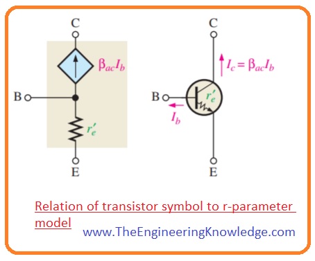
r-Parameter Transistor Model
- the r parameter model for bipolar junction transistor is shown in figure denoted as (a).
- For further analysis, the effect of base resistor r’b is less that can be ignored so it substituted with the short circuit.
- While the ac collector resistance r’c is numerous hundred kΩ so it can be substituted with the open circuit.
- The resultant simplified r-parameter corresponding circuit is shown in figure denoted as (b).
- The explanation of this model circuitry can be done as the resistance between emitter and base is observing into the emitter of forward bias.
- A collector is working as a dependent current source a , αacIe or equal to βacIb and denoted diamond shape symbol.
Determining re by a Formula
- For analysis of the amplifier the ac emitter resistance r’e is significant or r parameter.
- To find the estimated value of r’e you can use the below equation which is calculated by supposing an abrupt junction among the n and p regions.
- It depends on the temperature and base on the ambient temperature of twenty centigrade.
r’e=25mV/IE
- the value of numerator will be high for larger temperature or transistor having gradual junction.
- Though these conditions will result comparatively different consequences, mostly designs are not usually depending on the value of emitter resistance r’e and we will get good results with the use of the above equation.
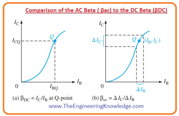
Comparison of the AC Beta ( βac) to the DC Beta ( βDC)
- The graphical representation for between IC and IB for a typical transistor is not linear as drawn in the below figure.
- If you take a Q-point on the graphical curve and vary the base current to value ΔIB then the collector current changes ΔIC as shown in figure denoted as (b).
- There will be different values of ratio ΔIc/ΔIB for different points of curve.
- It can also be different from the ratio IC/IB at Q point.
As βDC=IC/IB and βAC= ΔIc/ΔIB
h Parameters
- The datasheet of the transistor manufacturer specifies the parameter h or hybrid (hi, hr, hf, and ho) because these parameters can be easily measured.
- In every below figure, the explanation of 4 main ac ‘h’ parameters are shown.
- Every h parameter has a subscript that denotes the common emitter (e), common base (b) or common collector (c) amplifier structure.
- Here the term common denoted one of three-terminal E, B or C which is referenced to ac ground for both input and output waveforms.
Relationships of h Parameters and r Parameters
- The ratios of alternating current, transform directly from h parameters as.
αac = hfb
βac = hfe
- Since datasheets often offer only on h parameter of common emitter the below-given formulas explains how to transform them into the r parameter.
R’e=hre/hoe
R’c=(hre+1)/hoe
R’b=hie-hre/hoe(1+hfe)
So, friends, it is a detailed post about Transistor or BJT AC Models if you have any post about Transistor or BJT AC Models ask in comments. Thanks for reading.


