 Hello friends, I hope you all are doing great. In today’s tutorial, we will have a look at the Introduction to Darlington Pair configuration and its applications. The Darlington pair also called Darlington transistor it was the first time created in 1953 by the United States electrical engineer Sidney Darlington due to that it called Darlington. In this configuration, two transistors are connected with each other.
Both transistors configure such that emitter of one transistor given bias current to another transistor base .there are numerous applications where this transistor configuration is used such as power regulator, motor control circuits, etc. In today’s post, we will have a detailed look at its working, circuit, application and some other related parameters. So let’s get started with Introduction to Darlington Pair.
Introduction to Darlington Pair
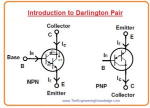
- The Darlington pair transistor consists of two transistors that is connected such that have complete packaging consist of an emitter, base, and collector like a single transistor.
- The gain providing by this transistor is very large as compared to the single transistor.
- This pair of transistors in this arrangement can be of PNP or NPN according to the application requirements.
- In a given diagram, you can see both NPN and PNP configuration of Darlington pair.
- Let’s assume that we have Darlington pair constructed with the NPN transistor.
- In this arrangement, a small base current generates a large value of emitter current that is given to the second transistor.
- The current amplified through the first transistor is again amplified with the second transistor.
- So current generated at the emitter of the second transistor is very high can any large current usage load.
- Let’s assume that gain current of first transistor is β1 and gain of the second transistor is (β2) so the net gain of this pair will be a product of these to gain β1. β2.
- The value of β for a standard transistor is one hundred. So-net current gain of Darlington pair will be ten thousand as it is a product of two transistors.
- This gain is very large than a gain of a single transistor. So this large gain provides a large current for load.
- Normally to on the transistor, the base input voltage should be larger than 0.7 volts.
- As the 2 transistors are working in this pair so for voltage at the base should be greater than 1.4 volts.
- From the given figure.
β1=IC1/IB1
C1= (β1IB1)
- Same this current gain for next transistor will be.
β2= (IC2/IB2),
IC2 = (β2 .IB2)
- The current at the collector will be some of two currents.
IC=IC1+IC2
IC= (β1.IB1) + (β2.IB2)
- Base current for second transistor will be given as.
IB2= (IB + IC1)
IB2= (IB + IC1)
IB2 = IB.(1+β1)
- By putting value we have.
IC = β1IB +β2IB(1+β1)
IC= IB(β1+β2+β1.β2)
- After neglecting individual gain we have resultant equation.
IC= IB(β1β2)
So net gain is.
β=(β1β2)
Darlington Transistor Applications
- This configuration of a transistor is normally used in switching and amplifier circuits.
NPN Darlington Transistor as Switch
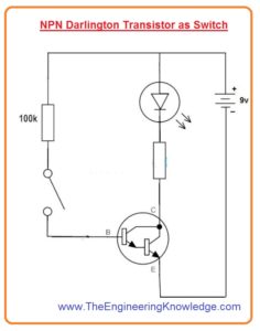
- The given diagram shows the running of LED with the Darlington pair.
- The switch at the base can be substituted with a touching sensor so after touching led operates.
- The one hundred ohm resistance in a circuit is used to provide protection to the pair.
- When the switch is closed then certain value of voltage larger than the 1.4 volts is given to the pair.
- Due to that voltage pair become active and current passes through the load.
- Due to that light-emitting diode emits light of high intensity irrespective of variation in base resistance.
- When a switch is unclosed both transistors are in a cutoff of mode of operation and a current flowing through the load is 0. Hence led turn off
PNP Darlington Transistor as Switch
- Now we discuss Darlington pair which is constructed with the PNP transistor.
- The configuration for PNP pair is almost the same as the NPN transistor.
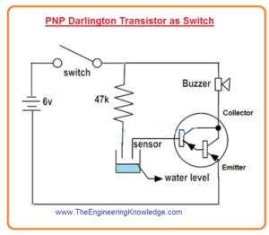
- The given figure shows a circuit for the alarm which will function through the Darlington pair.
- This circuitry is for water level indicator and Darlington pair operates as a switch.
- As Darlington pair gives large collector current so it will operate bell connected with as output to the circuitry.
- If the level is not high that will close the sensor Darlington is in off condition.
- Therefore, the circuit is open and no current flows.
- With the increment of water level sensor gets active and provides base current to Darlington pair which is required.
- Due to that circuity gets shorted and load current flows due to that buzzer or bell operate.
Darlington Pair Advantages
- These are some advantages of Darlington pair transistor.
- It generates a very large current gain than the one transistor.
- It provides very large input impedance or transformation of impedance so it can change input impedance from high to low or low to high.
- These modules consist of two transistors and available in a single casing.
- Due to the use of fewer components its configuration is less complicated.
Darlington Pair disadvantages
- Its switching process takes some time or slow.
- Its bandwidth is limited.
- It generates a phase shift for at specific frequency in negative feedback circuitry.
- Base emitter voltage is large and 2 times than the single transistor.
- It has large power dissipation due to the large saturation voltage.
- In this configuration leakage current is large which amplified the second transistor after first.
So, friends, it is a detailed post about Darlington pair if you have any questions ask in comments. Thanks for reading. See you in the next post.


