 Hello fellows, I hope you are doing great. In today’s tutorial, we will have a look at Introduction to Zener Diode. The diode is an instrument that has two terminals called cathode and anode used for conversion of AC into DC current. For conversion of AC into DC, rectifier circuits are used there are two types of rectifiers are used first is half-wave rectifier and the second one is a full-wave rectifier. The process of ac to dc conversion is called rectification. The normal diode operates in forward biasing condition current flows through it and in reverse bias condition current does not flows through diode.
There is a special purpose diode that operates in both reverse and forward biased condition that known as Zener diode. In today’s post, we will have a detailed look at its practical applications and used in different instruments. So let’s get started with Zener Diode Applications.
Zener Diode Applications
- The Zener diode is such a semiconductor diode that operates in both reverse and forward biasing mode.
- For operation in reverse biased mode, Zener diode has a high level of PN junction doping.
- To operate in reverse biased mode there is a specified value of reverse breakdown voltage for Zener over which it starts conducting in reverse biasing mode and continues operation in this region without any damage.
- The value of voltage loss across the diode is similar for different values of voltage due to this it can be used for voltage regulation.
Zener Regulation with Variable Input Voltage
- Regulators consist of Zener diode can be used to deliver the constant value of dc at the output terminals but normally not good.
- For this reason, they are used only for such circuits that operate on the less current.
- In the below figure you can see that diode is used to regulate the dc voltage.

- If we increase or decrease the input voltage of this circuitry within limit the output of Zener diode remains constant irrespective variation in the input voltages.
- As we are varying the VIN Iz will are in direct relation to VIN so that the limits on the input voltage changes are fixed by the least and extreme current values (IZK and IZM) with which the Zener can function.
- In circuitry, resistance denoted as R is a series current limiting resistance used to limit current at save condition.
- The multimeter used in a circuit will display the resultant values.
- For a practical understanding of voltage regulation through Zener lets construct a circuit having 1N4740A Zener diode.
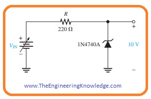
- The absolute lowermost current which will retain regulation is stated at IZK that is for 1N4740A is 0.25 milliampere and denotes the no-load current.
- The extreme value of current is not provided on the data sheet but can be found from the power description of one watt, that is written on the datasheet.
IZM = PD(max)/ VZ = 1 Watt/10 Volts = 100 mA
- For less value of zener current the voltage across resistance will be.
VR = IZKR = (0.25 mA)(220 Ω) = 55 mV
- as VR = VIN – VZ
VIN(min) = VR + VZ = (55 mV + 10 Volts) = 10.055 Volts
- For maximum value of zener current the voltage around resistance will be given as.
VR = IZMR = (100 mA)(220 Ω) = 22 Volts
- so
VIN(max) = (22 Volts + 10 Volts) = 32 Volts
- From this we can observe that this zener diode can vary or regulate voltage from 10.055 to 32 volts at input and retain an about 10 Volts output.
- There will be some variation in output as due resistance of Zener that we not considered in the above measurements.
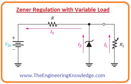
Zener Regulation with Variable Load
- In the below figure you can see the Zener voltage regulator circuitry having variable resistance as load.
- Zener diode provides a constant value of voltage across a diode in the case of Zener current is larger than the IZK and less than IZM.
Zener Regulation From No Load to Full Load
- If open the output terminals of Zener regulator circuitry or RL= ∞ the value of load current will be zero all the current will flow through diode it is no load condition of a diode.
- If we attach resistance at the load terminals then the complete current of circuitry will be divided between Zener diode and load resistance RL.
- The total current from the resistance R will be constant until that Zener is regulating the voltage.
- With the decrement in load resistance RL, the load current IL upsurges and Zener current IZ will reduce.
- The Zener diode continue the voltage regulation till reaches its lowest value I
- At this point the IL is extreme, and a diode is in full load condition.
Wht is Zener Limiter
- With the applications of as voltage regulator Zener diode can be used to limit ac signal to the desired level.
- In below figure 3 main methods of Zener diode as limiter is shown.
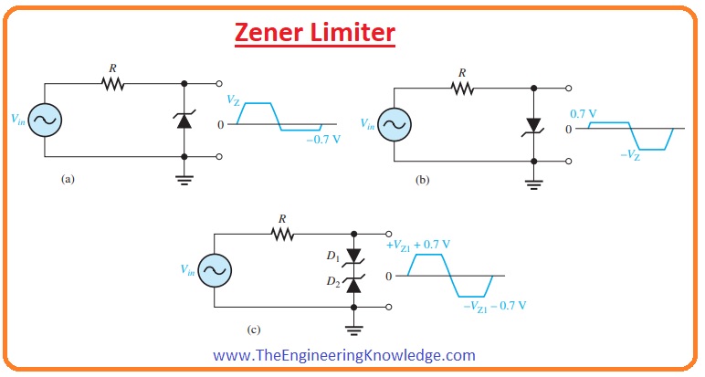
- The circuitry denoted as (a) explains the Zener working to limit the positive peal of the ac signal to set Zener voltage.
- When a negative cycle of signal comes across diode it operates in forward biasing condition restrict the negative part of the signal to -0.7 V.
- In-circuit denoted as (b) you can see the direction of diode in this circuitry is opposite to the direction of a diode in circuit dented as (a) the negative extreme of a signal is limited from the Zener action and positive portion is restricted to +0.7 V.
- In the circuit denoted as (c) two, didoes with opposite faces are shown that limit both extreme points of signal to 0.7volts.
- For the positive signal diode, D2 is operating as Zener limiter and Di is forward biasing.
- In the case of the negative part of the signal, D1 is operating as Zener limiter and D2 as forward biased.
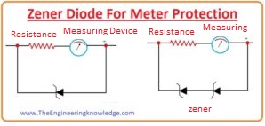
How to use Zener Diode For Meter Protection
- Zener diode is used in multimeter to provide protection to a meter in case of overloading.
- To provide protection to meter it connected in parallel with the diode as shown below.
- During overload condition, current increases and most of the current flows through the diode that protects the meter from damage.
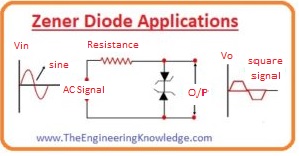
How to use Zener Diode for Wave Shaping
- Zener diode is used to transform ac sinusoidal signal into a square shape. The circuitry for this purpose is shown below.
- For positive and negative half of the wave when the input signal is less than the Zener value the resistance value is high.
- The input will be shown around the output points. When the input voltage is larger than the Zener value then resistance offered by the diode is less and large current flows.
- In consequence, large voltage loss appears around the resistance ‘R’ connected in series and henceforth the extreme of the input signal are clipped like clipper circuit as shown in the figure.
- The sinusoidal signal is converted into the square wave.
Related Post
- Current Regulator Diode
- Zener Diode
- Step Recovery Diode
- PIN Diode
- Schottky Diode
- Photodiode
- Varactor Diode
- Diode
- Zener diode Applications
- Laser Diode
- LED
So friends that is complete post about Zener diode applications if you have any further queries about this post ask in comments. Thanks for reading. See you in next post have a good day.


Awesome article.Really thank you! Much obliged.
Excellent read, I just passed this onto a friend who was doing a little research on that. And he actually bought me lunch because I located it for him smile So let me rephrase that: Thanks for lunch!