 Hello friends, I hope you all are doing great. In today’s tutorial, we will have a look at Introduction to Step Recovery Diode. Step recovery diode is also known as a charge storage diode or snap-off diode. In different electrical and electronic circuits, this diode is used to produce small pulses. It also used in such circuits where microwaves are used, this diode is used as a pulse generator or parametric amplifier.
In today’s post, we will have a detailed look at its working, construction, practical applications and some other related parameters. So let’s get started with Introduction to Step Recovery Diode.
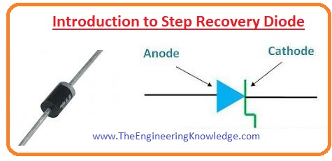
Introduction to Step Recovery Diode
- The step recovery diode is a diode that has less doping level as compared to other diodes and known as a voltage-dependent variable capacitor.
- The doping level in this diode is very less near to the junction of the diode. From this, we can say that charge carries are also less around the junction of the diode.
- Due to this charging is less close to PN junction of diode that decreases the time from on condition to off condition of a diode.
- As this diode provides high switching speed at less frequency so it mostly used as a charge controlled switch.
- At less frequency, this diode operates like a general diode that operates in forward biased condition and not flows current through a diode in reverse biasing conditions.
- Its condition changes very fastly as it changed biasing from forward biased condition to reverse bias.
- For larger frequency signals the switching of a diode is slow. Therefor current generated in forward biasing continue to flow in reverse biased cycle for some time interval.
- It is due to that stored charged close to PN junction, though their quantity is less but has a high frequency that uses the large time to move away from the junction.
- The number of charge carries reduces as they reach the junction this process reverse snap off exits. So step recovery diode is also known as Snap-off Diode.
Step Recovery Diode Construction
- The construction technique of the step recovery diode is alike to the general diode. The main difference between these diodes is their doping level.
- The doping process of a diode is shown in the below figure.
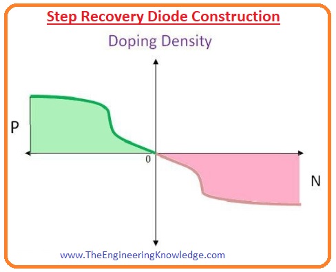
- You can observe from the figure that doping level of diode decreases as moves towards the junction of diode.
- These phenomena reduce the intensity of the moveable charge carries at the junction of the diode.
- This is necessary to get fast switching from a step recovery diode.
Step Recovery Diode Working
- As we have discussed earlier that step recovery diode operation is similar to normal diode for less frequency.
- At the start, the impedance of this diode is less almost one ohm with the storage of charging the impedance increases at the junction of diode.
- When there is negative half of input signal is provided to diode there stored charges in diode take some time to leave the junction due to that there is a small number of current flows at the starting of negative input half signal.
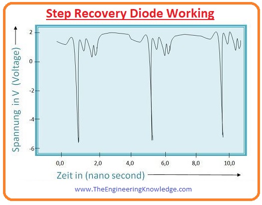
- The switching of this diode takes less time almost some ‘ns’.This imparts the capability to produce very sharp beats which play an important function in waveshaping circuits.
Step Recovery Diode Advantages
- These are some advantages of a step recovery diode.
High Forward Current:
- It produces the forward current speedily than the normal diode.
Fast Switching Time:
- Its switching time is very less.
Sharp Harmonics:
- This diode produces sharp pulses that are very useful for pulse generation circuits.
Step Recovery Diode Disadvantages
- Its drawback is that switching speed reduces with the increment in frequency.
Step Recovery Diode Applications
- These are some applications of step recovery diode.
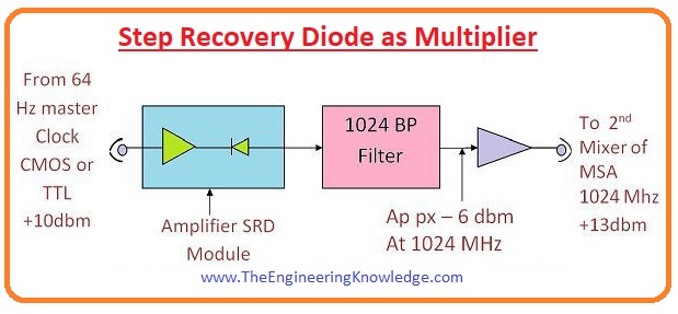
Step Recovery Diode as Multiplier:
- They can multiply the frequency of the signal up to 20 times. The fast switching time of Step recovery diode imparts them the ability to generate sharp pulses. During forward biasing they store charge and when reversed biased they use this charge to generate harmonics.
- Step recovery diode can be used to multiply the frequency of signal up to twenty times. Due to fast switching, the step recovery diode produces sharp pulses.
- When a diode is in forward biasing conditions its stores charges and during reverse biasing use these charges to produce harmonics.
- This phenomenon can be understood by the circuit shown in the below figure.
- The upsurge time of pulses produced by the diode is equal to snap time. The filtering circuitry gets the signal of the required frequency.
- The cut off frequency of this diode is from two hundred gigahertz to three hundred gigahertz.
- The large cut off frequency of diode makes the diode suitable for multiplier circuitry functioning at a frequency of almost ten gigahertz.
Harmonic Generators:
- The features of the step recovery diode to produce sharp pulses make it a good option to use as a harmonic generator.
- The circuitry of voltage-controlled oscillators used a step recovery diode.
- The circuitry of a frequency synthesizer consists of a step recovery diode.
Comb Generator:
- For the generation of numerous harmonics of an input signal used in comb generator.
- The output signal has a shape like to the comb teeth due to that is known as a combe generator.
Related Posts
- Current Regulator Diode
- Zener Diode
- Step Recovery Diode
- PIN Diode
- Schottky Diode
- Photodiode
- Varactor Diode
- Diode
- Zener diode Applications
- Laser Diode
- LED
So, friends, it is a detailed post about step recovery diode I tried my level best to make it simple and easy for you. If you have any queries about step recovery diode ask in comments. See you in next post have a good day.