 Hello, friends, I hope all of you are enjoying your life. In today’s tutorial, we will have a look at Full Wave Rectifier. The rectifier is a circuit used to convert alternating current into direct current in these circuit diodes is used for AC to DC conversion as it allows the flow of current in one direction. There are two types of rectifiers first one half wave rectifier and second is a full rectifier. In half-wave rectifier, a positive half of ac signal is converted into DC. The circuit of half-wave rectifier consists of one diode that operates only in forward biasing mode and rectifies only a positive half of AC current.
The full-wave rectifier consists of two or four diodes that connected in such an arrangement that they convert both cycles of ac signal into the direct current. In today’s post we will have a detailed look at its circuit, working, and practical implementation. So let’s get started with the Full Wave Rectifier.
Full Wave Rectifier
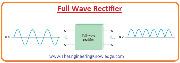
- Contrary to the half-wave rectifier circuit full-wave rectifier transforms complete ac waveform into the direct current.
- The frequency of output obtained by the full-wave rectifier circuit is double the frequency of input signal. As it is shown in the below figure.
- The output of the full-wave rectifier circuit is 2 times the output of half-wave rectifier is due to the positive fluctuation.
- The average value of the full-wave rectifier circuit calculated with the dc voltmeter is double the half-wave rectifier circuit and written below.
VAVG =2Vp/Π
- VAVG is almost 63.7 percent of Vp (peak voltage) for a full-wave rectified voltage.
Center-Tapped Full-Wave Rectifier Operation
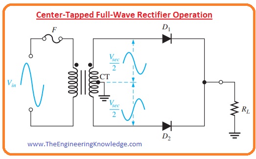
- In this type of full-wave rectifier, a center-tapped transformer is connected with the two diodes. This arrangement of a full-wave rectifier is shown in below figure.
- The input voltage at the primary windings of transformer is divided into two parts of secondary windings.
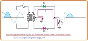
- In given figure the circuit behavior for the positive half of input voltage is shown.
- During a positive half cycle of input voltage, only diode D1 operates as it is forward biased and D2 diode is reversed biased so current will not flow through this diode.
- So during a positive half-cycle current will flow through the diode D1 and load resistance RL.
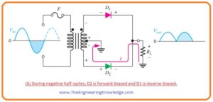
- For negative half of the input cycle, the given circuit is shown.
- In this condition, the diode D1 will be reversed biased and diode D2 is forward biased.
- So current will flow through the diode D2 and load resistance RL.
- Due to the forward biasing of both diodes for half cycles of input the complete input signal will be converted into the direct current.
Effect of the Turns Ratio on the Output Voltage
- Now we discuss the effect of transformer turn ratio on the output voltage of centered tapped transformer full-wave rectifier.
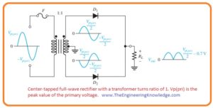
- If the number of turns in primary windings and secondary windings is equal then the turn of ratio of a transformer will be one.
- So in one turn ratio the rectified peak voltage equal to the half value of input voltage at the primary side minus the voltage across a potential barrier. It is shown in a given figure.
- Half the value of voltage at the primary windings will be divided into 2 parts of secondary windings.(Vp(sec) = Vp(pri))
- So we will define the forward voltage due to pontential barrier as a diode drop.
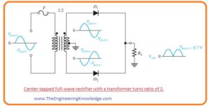
- To minimize the voltage drop across the potential barrier and to make an output voltage peak equal to the input voltage peak we used transformer having turn ratio 2. It is shown in the below figure.
- So the value of voltage at secondary windings of transformer is double the voltage at primary windings.
- Due to double voltage at secondary side, half value of voltage will appear across the half part of the secondary winding and equal to the Vpri.
- So we concluded one point here that it does not matter what value of turn ratio is the value of rectified voltage output of center-tapped rectifier is always half of total secondary voltage minus diode drop or potential barrier voltage.
Vout =(Vsec /2)- 0.7 V
Peak Inverse Voltage Center Tapped Rectifier
- Every diode in full-wave rectifier circuit shows two types of biasing mode forward bias and reverse biasing mode.
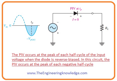
- The extreme value of reversed that can diode bear is peak secondary voltage Vp(sec).
- In given below figure there are 2 diodes, suppose that red color diode D2 is reversed biased and green color diode D1 is forward biased.
- When the polarity of secondary side (Vsec) voltage is according to figure.
- Then the extreme value of voltage across the diode D1 will be +Vp(sec) /2 and the value of extreme voltage across the diode D2 is -Vp(sec) /2.
- As the diode D1 is in forward biased condition so voltage at its cathode will be equal to the value of the voltage at anode minus the diode drop voltage.
- This condition is similar to the cathode of diode D2.
- The value of peak inverse voltage across diode D2 is given as.
PIV = ((Vp(sec)/2)-0.7) – (-Vp(sec)/2))
= Vp(sec)/2 + Vp(sec)/2 -0.7 volts
PIV= Vp(sec) -0.7—–(a)
- As Vp(out) = Vp(sec) -0.7V, if we multiply each term with the two and take transpose of it then we have.
Vp(sec) = 2Vp(out) + 1.4 V—(b)
- So putting value Vp(sec) in the equation a than the value of peak inverse voltage (PIV) across every diode in full-wave center-tapped rectifier is given as.
PIV= 2Vp(out) + 0.7 V
Bridge Full-Wave Rectifier Operation
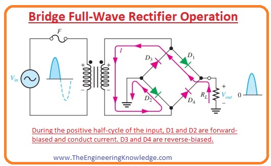
- In bridge full-wave rectifier circuit 4 diodes are connected in arrangements as shown in below figure.
- When the positive cycle of an input signal is passed through the circuit than diode D1 and D2 are in forward biased conditions and current flows across the path shown in the above figure.
- Due to this current, the voltage will be across the resistance RL and during positive cycle diode D3 and D4 are in reversed biased conditions.
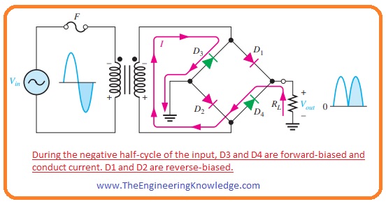
- When a negative cycle of an input signal comes across the bridge circuit than diodes D3 and D4 are in forward biased conditions and current will flow according to the path shown below figure.
- The output voltages of the full-wave rectifier will be across the resistance RL.
Bridge Rectifier Output Voltage
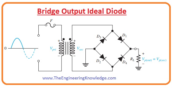
- In given below figure a bridge rectifier circuit taking input supply through the transformer.
- Due to the positive cycle of voltage across the transformer secondary windings diodes D1 and D2 are forward biased and by ignoring (ideal diode) voltage losses across diode complete voltage will be across the load resistance RL.
- During negative half cycle diodes, D3 and D4 are forward bias conditions.
Vp(out) = Vp(sec)
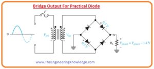
- In the below figure, you can see 2 diodes are in series with the load resistance if we take into consideration than the output voltage of the bridge rectifier circuit will be given as.
Vp(out) =Vp(sec) -1.4 V
Bridge Rectifier Peak Inverse Voltage
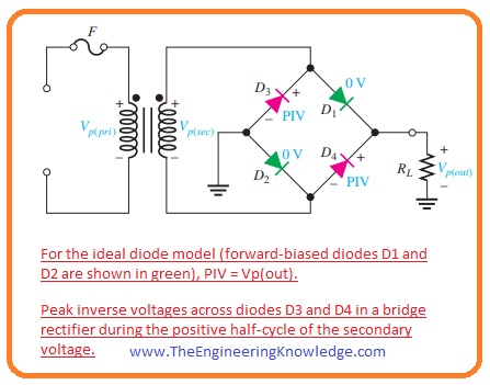
- Let’s suppose that diodes D1 and D2 are in forward biased condition and if we observe the voltage across diodes D3 and D4 then we will find that peak inverse voltage across diodes D3 and D4 is equal to the peak value of secondary voltage.
- As output voltage in an ideal case is equal to the voltage across secondary windings of the transformer.
PIV = Vp(out)
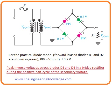
- If we also add voltage drop across diode during forward bises as shown in below figure then the PIV across every reversed biasing diode in the form of Vp(out) is given here.
PIV =Vp(out) – 0.7 V
- So if we compare both bridge and center-tapped rectifier diode peak inverse voltage ratings than we will come to know that PIV of bridge diode is less than the center-tapped rectifier.
- If we ignore the voltage drop across diode the bridge rectifier needs diodes with half the peak inverse voltage values of those in a center-tapped rectifier for the similar output voltage.
So friends that is a complete tutorial about Full Wave Rectifier I have mentioned each and every parameter related to this post ask in comments. See you in the next tutorial. Have a good day.



I’d always want to be update on new posts on this internet site, bookmarked! .
Grwat post! We will be linking to this great post on our website.
Keep up the great writing.
Excellent post! We will be linking to this great article on our site. Keep up the great writing.