 Hello guys, I hope you are doing great. In today’s tutorial, we will have a look at Diode Clamper Circuits. In a previous tutorial, we discuss the diode limiter circuits that limit the value of input ac waveform to the desired value and cut the signal above that level. While clampers are such circuits that vary the DC level of input ac signal from one point to another but not vary the level of signal similar to the limiter. In simple words, these circuits shift the positive peak and negative peak of the input signal. For this shifting DC, a component is added or minus from input signal according to the shifting position of the signal.
If a signal is to be shifted above the center-line of wave clamping circuit add the dc component and if the signal is to shifted below the center-line than the clamper subtracts the dc component from the input ac signal. If the clamper circuit shifts the input signal to above of the center axis than it called positive clamper. If the clamper shifts the signal below the axis then this circuit called negative clamper. The circuit arrangement of clamper is alike to the diode limiter or clipper circuits. But the difference is that with the diode and resistance clamper circuits have an additional capacitor. The capacitor provides the dc component from the charged stored on its plates. In today’s post, we will have a detailed look at its construction, working, and some other related parameters. So let’s get started with the Diode Clamper Circuits.
Diode Clamper Circuits
- The clamper circuits are also known as dc resistors. The main function of these circuits is to add some dc level into the input ac signal.
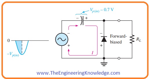
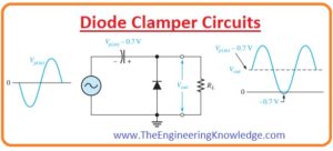
- In the below figure the clamper circuit is shown that is adding a positive dc level in the input ac signal.
- For practical working of this circuit suppose that the negative cycle of a wave is passing through the diode.
- During negative half of the signal diode is in forward biased condition due to that capacitor in the clamper circuit get charges to value (Vp(in) – 0.7 V) as shown in above figure.
- Diode becomes reversed biased after the negative peak of the signal.
- It is due to the cathode is placed close to Vp(in) – 0.7 V that is charge value on a capacitor.
- The charge can release its stored charge across the load resistance RL.
- So variation in the signal from one negative half cycle to other capacitor losses less value of the charge.
- The release of the charge depends on the load resistor RL.
- The clamping action can be disturbed if the capacitor loses it’s charging during the period of an input signal.
- The efficiency of clamper circuits will high if RC that is time constant is a hundred times the period of an input signal.
- If the time constant is 10 times the period of input signal than it will have a less alteration (distortion) at ground level due to charging current.
- The final effect of clamping circuits is that the capacitor keeps a charge almost equivalent to the extreme (peak value) of input signal minus voltage drop across diode.
- The voltage provided by the capacitor operates like a battery connected in series with the input signal.
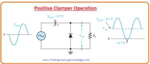
- The dc voltage provided by the capacitor will sum up with the input signal and superimposed with it. As shown in below figure.
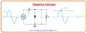
- If we vary the diode position then the negative dc voltage is added with the input signal to generate output similar to shown in the below figure and this type of circuit arrangement is called negative clamper.
Diode Clamper Circuits Types
- There are 3 main categories of clamper circuits that are listed here.
- Positive Clamper Circuits
- Biased Clamper Circuits
- Negative Clamper Circuits
- Let’s discuss them with the detailed.
Positive Clamper Circuits
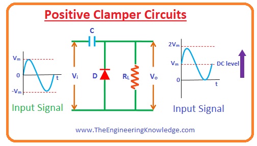
- In the below figure you can see the circuit arrangments of positive clamper circuits. This circuit consists of a voltage source Vi capacitor C, diode and load resistance.
- The diode is linked with the load resistor RL in parallel combination. Due to this arrangement, positive clamper circuits will allow to pass input waveform when a diode is in reversed biased condition and stops input signal to flow when diode is in forward biased condition.
For Input Negative Half Cycle
- When a negative cycle of input waveform comes across the diode it is in forward biased condition and it allows current to flow through the load resistance.
- Due to this current capacitor get charged to the Vm that is the peak value of input waveform.
- The charging polarity of capacitor is opposite to signal polarity across a diode. After reaching the extreme point -Vm the capacitor retains the stored charged til that point diode is in forward biased condition.
For Input Negative Half Cycle
- When positive half of the input signal passes through the diode it is in reverse biased condition and no current flow through the diode.
- Due to that, zero current across diode input signal flows towards the load resistance.
- During a positive cycle, a diode is not in an operating condition so the capacitor releases its stored charge.
- So the voltage across the load resistance will the addition of voltage across the capacitor Vm due to the charge store and voltage provided by the input source Vm. (Vo= Vm+ Vm = 2Vm). The polarity of these 2 voltages is also similar.
- As a consequence, the signal moved to upward that happens in positive clamper circuits.
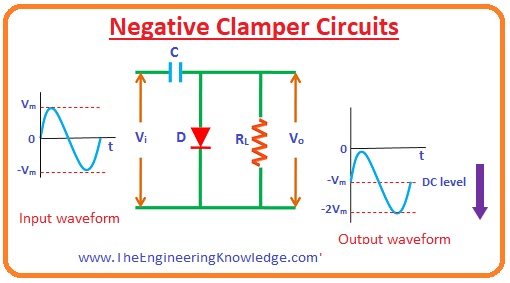
Negative Clamper Circuits
For positive Input Half cycle:
- When a positive cycle is passed through the circuitry the diode is in forward biasing condition due to that zero signal exits across the load resistance.
- Due forward biasing of diode current passes through the load resistance.
- Due to this current capacitor gets charged to the extreme value of input signal with the opposite polarity (-Vm) and this charge remains till that point diode is in forward biased condition.
For Negative Input Half Cyle:
- When a negative cycle comes across circuit diode is in reverse biasing condition so signal exits across load resistance.
- Due to reverse biasing current does not flows through the diode. So the current coming from the input source moves towards the load resistance.
- During the negative half, a diode is in a non-operating state and the charge stored on diode will disappear.
- So the voltage across the load resistance will be an addition of voltage across a capacitor -Vm and voltage due to input source -Vm that is (-2Vm). Due to that original signal moved below the x-axis.
Diode Biased Clamper
- In certain circuits, there is a need of an additional shift in DC level of the input signal. For these purposes, diode biased clampers are used.
- The operation of biased clampers is alike to the unbiased clamper circuits that we have discussed above with the detailed.
- The difference between biased and unbiased circuits is that in biased circuits additional DC source is used for DC element.
- Let’s discuss different types of biased clampers.
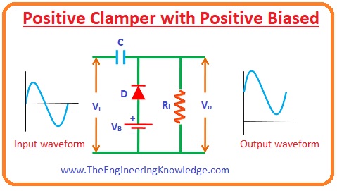
Positive Clamper with Positive Biased
- The biased clamper called positive clamper with positive biased if it has positive biasing in the circuitry.
- The circuitry has a dc source or dc supply, load resistance, capacitor, and diode.
For Positive Input Half Cycle
- When the positive cycle of input source is across the diode then dc source attached with the diode makes it in forward biased condition when the value of input voltage due to input source is less ac compare to dc supply.
- Due to that current capacitor also gets charged.
- When the voltage provided by the input source is greater than the voltage of the DC source than current stops to flow through the diode as a diode is now in reversed biasing condition.
For Negative Half Cycle
- For negative half cycles of input supply and dc power supply, the diode is in forward biased condition.
- Due to this current flows through the diode. Due to this current capacitor gets charged.
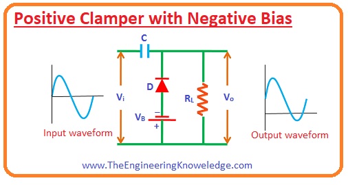
Positive Clamper with Negative Bias
For Negative Half Cycle
- For the negative half cycles due to battery, voltage diode becomes reverse biased if the battery voltages are larger than the input supply.
- Due to that, there will be signal exits across the load resistance.
- If the voltages of battery are less than the input supply voltages then current will pass through the diode contrary to reverse biased condition.
-
This current will charge the capacitor.
For Positive Half Cycle:
- For positive half cycles of battery and input source, the diode is in reverse biased condition. So the signal will exit across the load resistance.
- The magnitude of a signal across load resistance equals the addition of voltage due to input source and voltage across the capacitor.
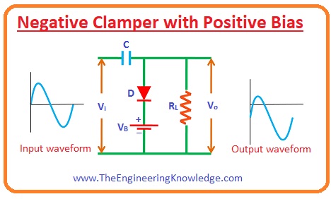
Negative Clamper with Positive Bias
For positive half-cycle:
- For the positive half, cycle diode is reversed biased due to the voltage of a battery it occurs if the input voltage is less than the voltage of the battery.
- When the voltage provided by the battery is less than the input source the diode is in forward biased condition due to the voltage of input source and current passes through the diode.
- Due to this current capacitor will get charged.
For Negative Half Cycle
- For both negative half cycles of input supply and battery, a diode is in reversed biased condition.
- Due to reverse biasing signal is exiting across the load resistance.
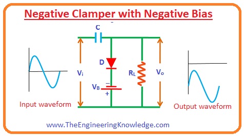
Negative Clamper with Negative Bias
For positive half-cycle:
- For both positive half of dc battery and voltage source diode is in forward biased condition.
- Due to this current will pass through the capacitor and it will charge.
For Negative Half Cycle:
- For the negative half cycle if the battery voltage is larger than the input voltage then a diode is in forward biased condition.
- As the value of input source voltage is larger than the voltage of battery diode is in reversed biased condition due to input voltage and now signal exits across the load resistance.
So friends that is the detailed post about Diode Clamper Circuits I have mentioned each and every parameter related to Diode Clamper Circuits. If you have any queries about this post ask in comments. See you in the next interesting post. Have a good day.


