Hello, fellows, I hope all of you are having fun in your life. In today’s tutorial, we will have a look at solid-state induction motor drives. An induction motor is a constant-speed and self-starting alternating current motor. It is known as a constant-speed motor because its speed is constant, relying on the frequency of the input supply and the number of windings of the motor.
In previous years, it was very difficult to control the speed of the induction motor according to our requirements. Due to this reason, these were not commonly used; instead, these direct current motors were preferred, as induction motors are better than DC motors, but due to speed regulation, they were not used. But nowadays such devices for induction motors have been invented that control the speed of the induction motor and make them useful for such applications where constant speed is necessary. So let’s get started with solid-state induction motor drives.
.
Solid State Induction Motor Drives
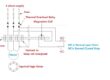
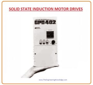
- Nowadays, the most used technique for the speed regulation of the induction motor is the solid-state variable frequency induction motor drive. You can see in the given figure a solid-state driver for an induction motor.
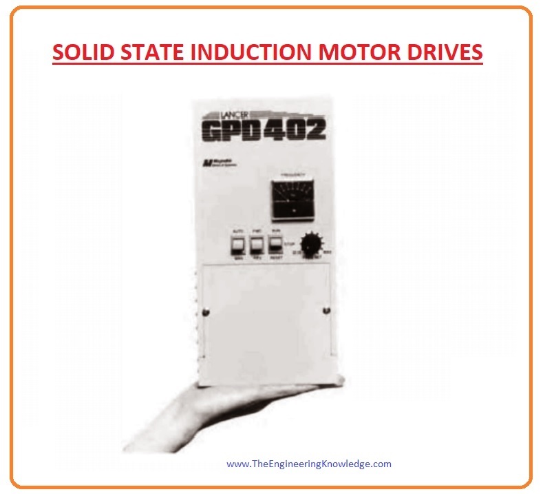
The flexibility of this drive is very high; it can be connected with the one-phase or 3-phase supply, it can also connect with a system that has a frequency of either fifty or sixty hertz, and it can also operate on a voltage range from two hundred eight to two hundred thirty volts.
The output of this solid-state drive is 3-phase, and its frequency can be changed from zero to one hundred twenty hertz, and its output voltage can be zero to the rated voltage of the motor.
The output voltage and frequency of this drive can be varied by using PWM (pulse width modulation).
The output voltage of the solid-state drive and output frequency can be varied autonomously with the PWM.
In the given figure, you can see that the pulse width modulation is controlling the output frequency by keeping the root mean square (rms) voltage at a constant level.

In this given figure we can see that the pulse width modulation varies the root mean square voltage by keeping the output frequency at a constant level.
As we have discussed in SPEED CONTROL OF INDUCTION MOTORS, it is frequently required to change the output frequency and output root mean square voltage together in a linear way.
The given diagram explains the output voltage wave for a single phase of the drive-in case when the voltage and frequency are both varying concurrently in a linear style.
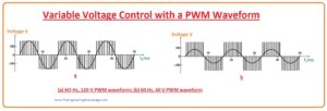
The figure that is denoted as (a) displays the output voltage regulation for a sixty-hertz frequency and root mean square voltage of one hundred twenty volts.
Figure denoted as (b) displays the output regulated for a thirty-hertz frequency and a root-mean-square sixty-volt voltage.
The figure that is denoted as “displays” the output regulated for a twenty-hertz frequency and forty volts of root-mean-square voltage.
We can note that the maximum output voltage of the solid-state drive is similar in all three waveforms; the value of the root mean square voltage can be regulated by the time at which the switch operates, and the value of the frequency is regulated by the rate when the pulse is changing form from a positive cycle to a negative cycle.

Frequency (Speed) Adjustment Induction Motor Drive
- The frequency at the output of the solid-state drive can be varied from a button manufactured on the body of the drive, or from a long distance it can be regulated by outer current or voltage signal.
- The capability to regulate the frequency of the drive by any outer signal has importance because it allows any exterior process monitor or computer to adjust the speed of the induction motor according to the need of the system with which the motor is connected.
Choice of Voltage and Frequency Patterns for Induction Motor drive
There are different categories of loads connected with the shaft of the motor. Like fans, the motor needs a lower value of torque at the initial stage, and its torque increases with the square of the speed.
There is such a load when connecting with the motor; it needs a larger amount of torque to rotate the load.
If we connect drivers with the motor, then it provides many options of voltage and frequency configurations that can be chosen to fulfill the torque requirement that the motor needs for different loads.
The diagram given below explains the standard or general-purpose voltage vs. frequency curve.
This shape varies the output voltage in a straight line with variation in output frequency for a speed less than the base speed and retains the same value of the output voltage for a speed greater than the base speed.
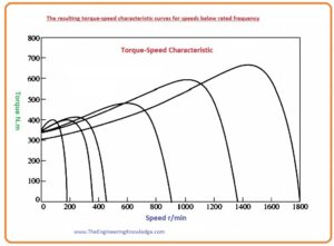
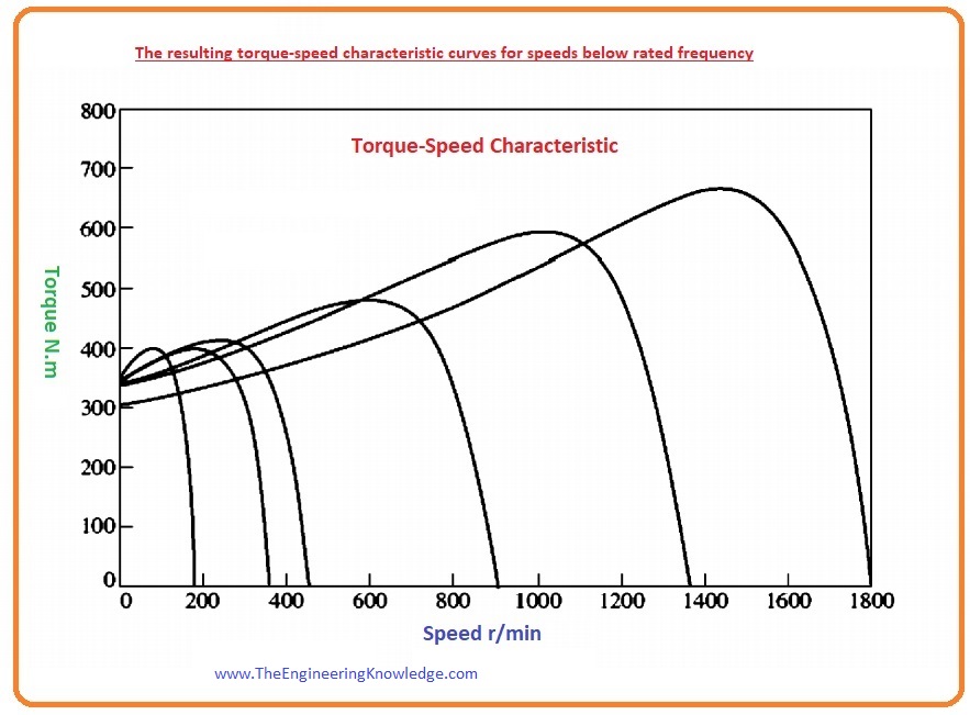
- The figure below explains the resultant induction torque-speed characteristics for numerous working frequencies less than the base speed.
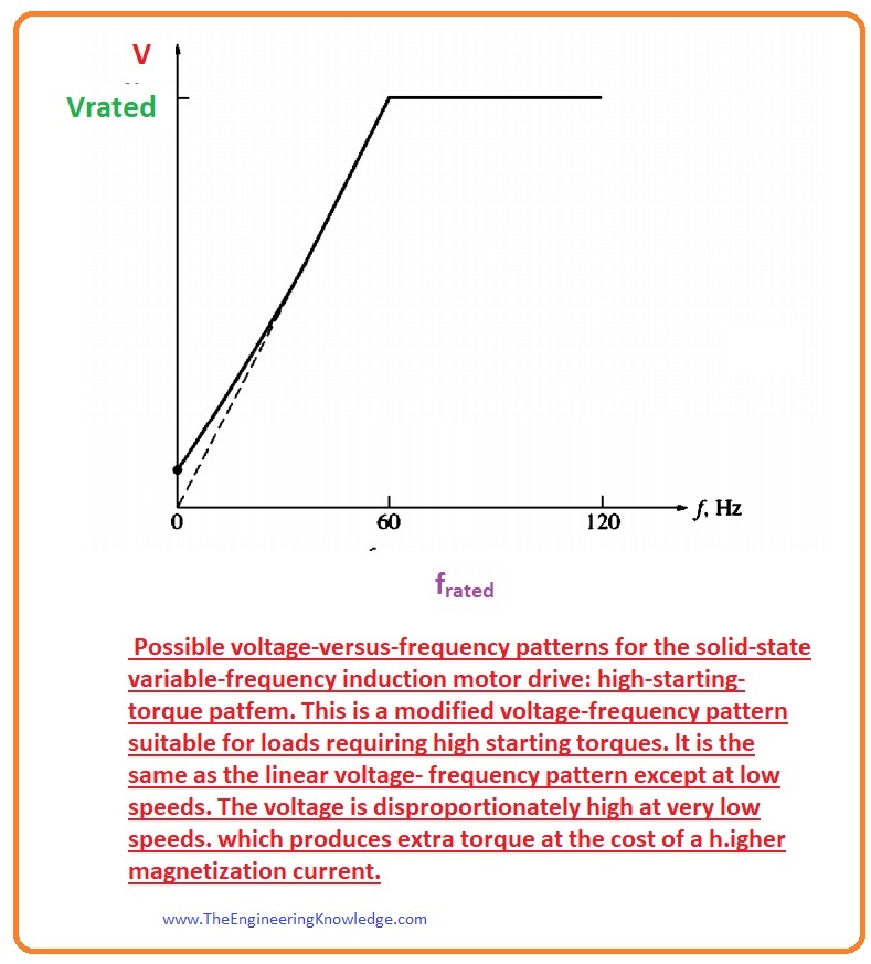
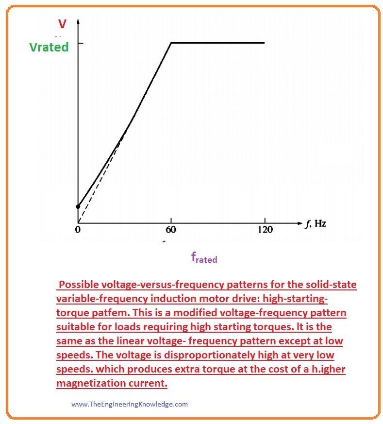
- In the diagram below, you can see the voltage-frequency curve for such a load that needs higher initial torque.
This design also varies the output voltage directly with variation in output frequency for speeds less than base speed, while the slope of the curve is lower at a frequency less than thirty hertz.
If the frequency is less than thirty hertz, the value of the output voltage will be larger than that we discussed in the above pattern.
This larger voltage will generate a larger value torque, but it also has one drawback: its magnetization current increases, and so does magnetic saturation.
The high saturation and larger magnetization current are sometimes bearable for small intervals to run the motor when it is connected with larger loads.
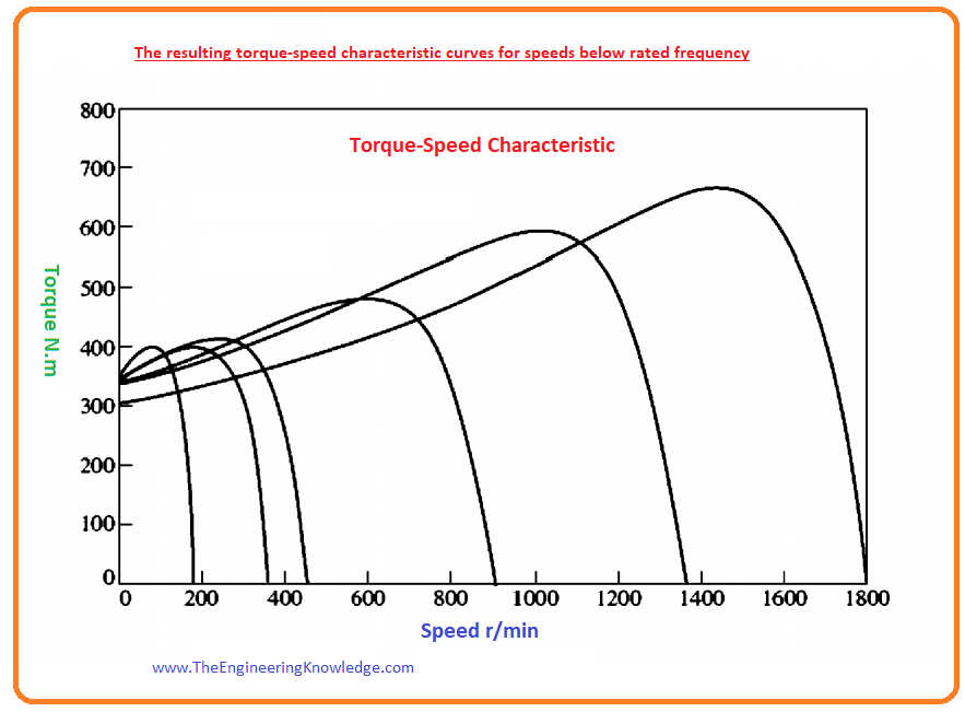
The given figure explains the induction motor torque-speed characteristics for many frequencies that are less than the base speed.
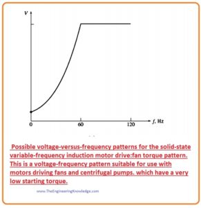
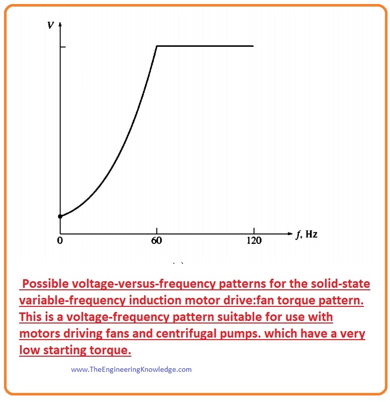
- In given below figure you can see the voltage-frequency curve for such a load that takes less value of the initial torque.
- The variation in the frequency for speeds less than the base speed will vary the output voltage like parabolic.
- For frequencies less than sixty hertz, the value of the output voltage will be less than standard values.
- This lower value of the voltage will induce less torque, which gives a sluggish, flat start for less-consuming torque loads.
- The figure below displays the induction motor torque-speed characteristics for numerous values of frequencies less than base speed.
Independently Adjustable Acceleration and Deceleration Ramps Induction Motor
- When the required speed of the motor varies, any motor drive that regulates the speed will vary the frequency to maintain the motor speed.
- If the speed variation is abrupt like it varies from nine hundred to twelve hundred revolutions per minute, the drive does not attempt to force the motor to promptly jump from the older required speed to the newer required speed.
- In its place, the rate with the motor is accelerating or decelerating is restricted to a safe point by distinct circuits constructed into the electronics part of the drive.
- These rates can be varied independently for acceleration and deceleration.
Induction Motor Protection
- The drives of the induction motor have lots of specifications for the protection of the motor that is attached to it.
- The motor’s drive can sense extreme steady-state currents during overloading of the motor, extreme instantaneous currents, over-voltage, or under-voltage disorders.
- If any fault occurs, the drive will disconnect the power supply of the motor.
You can also read some related articles to the induction motor. That is described here.
- Introduction to Induction Motor
- Introduction to Three Phase Induction Motor
- Equivalent Circuit Induction Motor
- Induction Motor Torque-Speed Characteristics
- Variations in Induction Motor Torque-Speed Characteristics
- Power and Torque in Induction Motors
- Induction Motor Design Classes
- speed Control Method of Induction Motors
- Induction Motor Design
It is a detailed post on the Solid State Induction Motor Drives if you have any queries, ask in the comments. Thanks for reading take care until the next tutorial, No Load Test of Induction Motor.