 Hello, fellows, I hope all of you are having fun in your life. In today’s tutorial, we will discuss Variations in Induction Motor Torque-Speed Characteristics. In the last tutorial Induction Motor Torque-Speed Characteristics, we find the different parameters of the torque and speed of the induction motor. Also, find the induced torque equation by solving the equivalent circuit of the induction motor. The main important thing we find the maximum (pullout) torque of the motor.
In today’s post, we will discuss some factors that varied the torque-speed Characteristics of the motor. For these factors, we take different types of rotors like deep rotor or double cage rotor and find the effect of the torque and speed on them. So let’s get started with Variations in Induction Motor Torque-Speed Characteristics.
Variations in Induction Motor Torque-Speed Characteristics
- In a previous article for torque-speed characteristics, we studied the different parameters related to that curve. Suppose if we have such rotor that has a higher value of the rotor resistance Rr due to this higher value of the resistance the starting torque will also larger, as the torque is higher so the slip will also higher.
- As we know that this equation.
Pconv = (1-s)PAG
- Due to the higher value of the slip, the power converted from the electrical to mechanical will have less value, due to less power conversion the efficiency of the motor will decrease.
- From that, we can conclude that such a motor that has higher rotor resistance has a larger starting torque but less efficiency.
- If the resistance of the rotor is less then the starting torque will also be less but the efficiency of the motor will be larger than the motor that has a high value of the rotor’s resistance.
- The manufacturer of the motor always tries to cooperate among the differing requirements of higher initial torque and suitable efficiency.
- The solution for this is that if we put some additional resistance in the rotor of the wound motor during its starting for higher torque then during its normal working remove this resistance for good efficiency.
- But there is a problem for this condition the wound rotor motor is costly, its repairing price is also larger, need multifaceted automatic control circuitry than cage rotor motors.
- Similarly, it is sometimes significant to entirely cover a motor when it is sited in a risky or fiery atmosphere, and this is calmer to do with an entirely self-contained rotor.
- It would be pleasing to add additional rotor resistance at initial and to eliminate it during normal operation without automatic control circuitry.
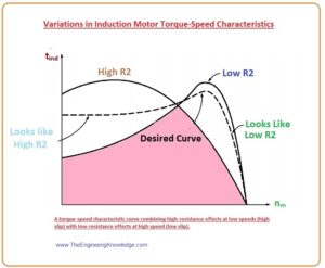
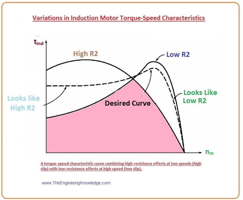
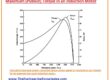
- In the given figure you can see the 2 wound rotor motors characteristic curves, one motor has high resistance rotor and the second has a less resistance rotor.
- At higher slip value, the anticipated motor should act like the higher-resistance wound-rotor motor curve and at less slip, it should act like the less-resistance wound-rotor motor curve.
Control of Induction Motor Characteristics by Cage Rotor Design
- The equivalent circuit of the induction motor the term X2 is leakage reactance. It is the reactance due to the flux of the rotor that does not interact with the stator of the motor.
- In a simple words, if the distance between the stator and the rotor bar is larger than the value of leaked reactance will be high, because less amount of the rotor flux approaches to the stator.
- So, if the bars of a cage rotor are located near the surface of the rotor, there will be less leakage flux due to less value of leakage flux the X2 will also lesser in the equivalent circuitry of the motor.
- If the rotor bars are positioned deeply into the rotor surface, the value of leaked flux will be higher so X2 will also higher.
- The given diagram shows the photo of a rotor lamination that explains the cross-section of the bars in the rotor
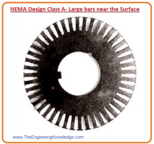
- The bars of the rotor has a larger cross-sectional area and are located at the surface of the rotor.
- As we know that R = pL /A, so due to larger areas of the bars they will have less resistance and the value of leakage reactance will also less as a bar is located at the surface of the rotor (near stator).
- Due to less value of the resistance of the rotor, the pullout torque almost equals to the synchronous speed and the motor will be very effectual.
Smax = R2/R2th + (Xth+X2)2
- As we know that
Pconv = (1-s)PAG
- So the small value of air gap power will be due to less value of the slip.
- Though, the rotor resistance R2 is less so the starting torque will also less and the starting current of the motor will be larger.
- This category of design is known as class A design of induction motor according to the (NEMA) (is the main trade association of electrical devices producers in the United States. It was originated in 1926)
- It is almost like the wound rotor induction motor that does not have additional resistance in the rotor circuit.
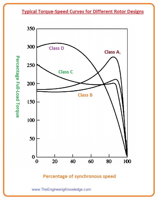
- The torque-speed characteristic of this motor is drawn here.
- But in the given diagram the rotor that has a less cross-sectional area bar located near the surface of the rotor.
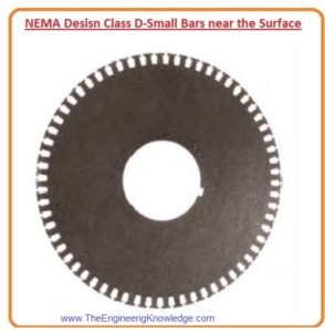
- Due to the smaller areas of the bars, the value of the resistance will be larger.
- As the bars are located at the surface of the rotor that means the distance between bars and the stator is less so the X2 is also less.
- This motor is similar to the wound rotor motor that has additional resistance added to its rotor circuitry.
- Due to larger resistance at the rotor, the starting torque will also higher with larger value slip.
- A cage motor with this kind of rotor structure is named NEMA design class D.
Deep-Bar and Double-Cage Rotor Design
- Both of the earlier rotor designs A and D are principally alike to a wound-rotor motor with a rotor resistance.
- One question here arises.
How can an adjustable rotor resistance be shaped to combine the higher starting torque and less starting current of a class D design with the less normal working slip and higher efficiency of a class A design?
- Yes, it is possible to make changeable rotor resistance if we use deep rotor bars or double cage rotors.
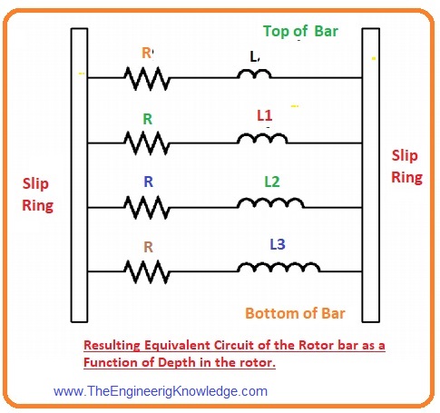
- The basic principle is explained in the given figure.
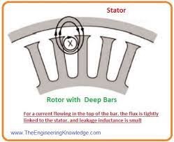
- You can see in the above-given figure that the current is moving in the upper portion of the deep rotor bar.
- As the upper part of the rotor is near to the stator so due to less distance, the X2 leakage inductance will be lesser, and larger flux will relate to the stator.
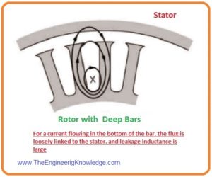
- In given below figure you can see that the current passes in the deep point of the rotor’s bar. At this point, the value of the leakage reactance will be larger.
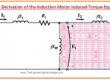
- As all portions of the rotor bar are connected in parallel, the bar basically signifies a series of parallel electrical circuitry, the upper circuits have a smaller inductance and the lower circuits have a large inductance. It is shown in the given picture.
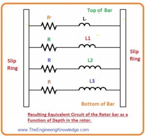
- At lesser slip, the frequency of the rotor is also less and the reactances of all the parallel circuits shown in the above figure are less than their resistances.
- The impedance of all parallel circuits of the rotor’s bar is almost equivalent, so current moves through all portions of the bar are also the same.

Double-Cage Rotor Design
- A view of the double cage rotor is shown in the given figure.
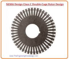
- It contains a larger, less-resistance set of bars inserted deeply in the rotor and a lesser, high-resistance set of bars put at the rotor’s upper part.
- It is similar to the deep-bar rotor, except that the difference between the less-slip and the higher-slip process is overstated.
- During the starting of the motor smaller area bars of rotor work, so it provides larger resistance due to that starting torque value is also higher.
- But, at normal functioning speeds, larger areas, and smaller areas both bars are operative, so the value of resistance is less like the deep bar rotor.
- Double-cage rotors of this category are used to construct NEMA class B and class C features. You can see this given equation for further explanations.
Disadvantage of Double cage Rotor
- There are some disadvantages to the double cage rotor that are described here.
- This type of rotor is expensive than other categories of the cage rotor.
- Their price is less than the wound rotors.
- They provide features like the wound rotor, such as higher initial torque with less starting current and good efficiency.
- The repairing cost of a deep bar rotor is less as compared to the wound rotor motor, as it does not have slip rings and brushes that wound rotor motor has.
So it is the complete tutorial on the Variations in Induction Motor Torque-Speed Characteristics if you have any query ask in the comments. Take it until the next post.
You can also read some related articles to the induction motor. That is described here.
- Introduction to Induction Motor
- Introduction to Three Phase Induction Motor
- Equivalent Circuit Induction Motor
- Induction Motor Torque-Speed Characteristics
- Variations in Induction Motor Torque-Speed Characteristics
- Power and Torque in Induction Motors
- Induction Motor Classes
- Induction Motor Design Classes
2 Comments