 Hello, fellows, I hope all of you are having fun in your life. In today’s tutorial, we will have a look at the Speed Control Method of Induction Motors. There are many motors working in our environment some are working in our homes and some in industries to make our working simplest. The electrical motor nowadays has become a crucial source of energy in our different engineering works. The purpose and the performance essential for these motors have many ranges. When we discuss the speed-controlling portion of different motors, then we know that the stepper motor and servo motors govern their speed by the pulse train or Pulse wave (A pulse wave or pulse train is a type of non-sinusoidal wave-form which includes square waves and similarly periodic but asymmetrical waves). But the induction motors and brushless DC motors govern (control) their speed with the exterior resistance or DC voltages.
The induction motors have a constant speed, which means that during all load variations, it has almost the same speed. Speed control of DC shunt motor can be changed without any loss in its efficiency, but in the case of induction motor speed, variations cause to decrease in its efficiency and power factor loss. As we know almost every industry and in our homes, an induction motor is working so its speed control factor is required in its many applications. In this post, we will discuss different methods of speed control of induction motors and their other parameters. So, let’s get started with the What are the Speed Control Method of Induction Motors.
What are the Speed Control Methods of Induction Motors
- Before the invention of current solid-state drives, induction motors were not considered suitable for such applications where speed variation is required.
- For normal working, an induction motor is restricted to work on the slip of less than the five percent, and speed changing on this range is almost directly proportionate to the load of the motor.
- However if we increase the slip of the motor, the efficiency will be decreased, as we have discussed that the copper loss at the rotor (PRCL) is directly proportionate to the slip (S) of the motor. Recall this formula.
PRCL = sPAG
- There are two methods by which the speed of the induction motor can be monitored (controlled).
- The first one is to change the synchronous speed (nsync) which is the speed of rotation of the magnetic field of the stator and the rotor.
- The second method is to change the slip (s) of a motor according to the load on the shaft of the motor.
- The synchronous speed (nsync) of an induction motor is given by this formula
(nsync) =120 (fe/p)
- From this equation, we can see that the first method by which we can vary synchronous speed is to vary the electrical frequency and the second is to change the no of poles of the motor.
- Slip control can be done by changing either the rotor resistor or the terminal voltage (VT) of the motor.
Speed Control Methods of Induction Motors
- There are many methods by which we can control the speed of the induction motor. These methods are described below.
- Induction Motor Speed Control by Pole Changing.
- Induction Motor Speed Control by Changing the Line Frequency.
- Induction Motor Speed Control by Changing the Line Voltage.
- Induction Motor Speed Control by Changing the Rotor Resistance.
Let’s discuss these methods one by one with the detail.
Induction Motor Speed Control by Pole Changing
- There are 2 ways by which we can vary the no of poles in induction motors to regulate the speed of the motor. These two are described below.
- Multiple stator wingdings.
- The method of consequent poles.
- The technique of pole variation is older, firstly it was used in 1897.
- This technique works on the fact that the poles in stating wingdings can be varied by the (2:1) factor just varying the connections of wingdings coil.
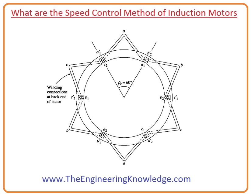
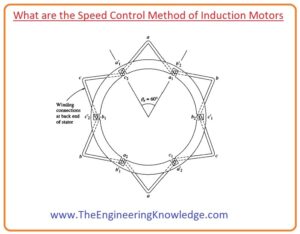
- In the given diagram, you can see that the stator of the 2-pole induction motor at which we have to apply the pole-changing technique.
- You can see from the diagram that every coil has a very low pitch value of about sixty to ninety degrees.
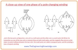
- Guys in given below diagram you can see that the phase winding is drawn separately for clear observation.
- We can see in the circuit which is a labeled in the diagram as (a) it describes the direction of current flowing in phase an of stator wingdings during normal working operation.
- You can see that the field left the stator in the upper phase group (N pole) and went in the stator in the lower phase group (S pole).
- These wingdings now make 2 poles at the stator.
- Now lets we assume that the direction of current (I) moving in the lower phase group on the stator is inverted then the field left stating part of the motor in both the lower phase and upper phase group everyone will behave like the north (N) pole. This phenomenon is shown in the diagram and its circuit is labeled as b in the diagram.
- The flux in this motor should come back to the stator among the 2 phase groups, which creates a couple of resultant south (S) magnetic poles.
- Note that now there are 4 poles on the stator two times more than the earlier motor has.
- The rotor in this motor has cage designing, as the cage rotor because this rotor always has the same no of poles as exists on the stator and it can very its pole as no of poles vary on the stator.
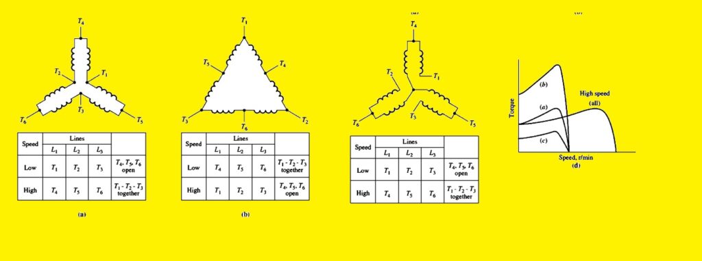
- When motor is re-connected from 2-pole to 4-pole operation, the resultant extreme torque of the induction motor can be the similar as earlier (constant-torque joining), half of its preceding value (square-law-torque assembly, which used for fans), or two time its preceding value (constant-output-power assembly), dependent on how the stator wingdings are re-positioned.
- The given diagram displays the probable stator contacts and their consequence on the torque-speed curve.
A disadvantage of the consequent-pole method of changing the speed
- The main drawback of the consequent-pole technique of speed variation speed should be in the ratio of (2:1).
- The old-style method to overcome this restriction was to use numerous stator wingdings with changed no of poles and to energize the one set of wingdings at a time.
- For instance, a motor might be wound with a 4-pole and a 6-pole set of stator wingdings, and its synchronous (nsyn) speed on a sixty-Hz scheme could be switched from (1800 to 1200 r/min) only by providing power to the other set of wingdings.
- Tactlessly, numerous stator wingdings upsurge the expenditure of the motor and are therefore used only when categorically essential.
- By joining the technique of resulting poles with numerous stator wingdings, it is thinkable to make a 4-speed induction motor.
- For instance, with isolated 4 and 6-pole wingdings, it is probable to make a sixty-Hz motor accomplished of running at (600, 900, 1200, and 1800 r/m).
Induction Motor Speed Control by Changing the Line Frequency
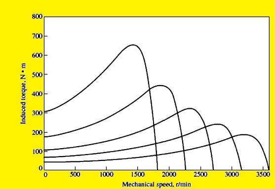
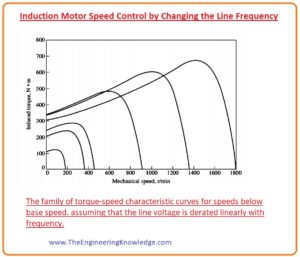
- If we change the frequency provided to the stator then the change in a rotational magnetic field will be directly proportional to the change in frequency and at the torque-speed curve, the location of no-load point will also vary you can observe this change in a given diagram.
- The synchronous speed (nsync ) of the motor at rated conditions is named as the Base Speed.
- By changing the frequency there is a possibility to set the speed of motor either less or higher the base speed.
- An accurately intended variable-frequency induction motor drive can be very flexible.
- It can change the speed of the motor from five percent less than two times the base speed.
- To ensure the continued and safe operation of the motor, during frequency variation there should be torque and voltage should be at certain level.
- When the motor is working at the speed less than the base speed, it is essential to decrease the applied voltage at the stator for the proper working of the motor.
- The decrease in the stator applied voltage should be linear with decrease in the stator frequency. This procedure is known as If we do not do this the saturation level of core material will increase which is steel and a large amount of magnetization current will pass through the motor.
What is Derating of Induction Motor
- To know the requirement for derating, recall that an induction motor is principally a revolving (rotating) transformer.
- As we know that the in the transformer the value of flux in the transformer’s core can be measured by Faraday’s law of Electromagnetic induction.
V(t) = -N (dø/dt)
- If a voltage (V(t) = VM Sinwt) is provided to the core, then resultant flux will be.
Ø(t)=1/Np
=1/Np
Ø(t)=Vm/wNP (coswt)
- You can see from the equation that the frequency exits at the denominator.
- So, if the frequency provided to the stator declines by ten percent whereas the magnitude of the voltage provided to the stator remains constant, the flux in the core of the motor will upsurge by almost ten percent and the magnetization current (Im) of the motor will upsurge.
- In the unsaturated portion of the motor’s magnetization curve, the upsurge in magnetization current (Im) will also be almost ten percent.
- Though, in the saturated region of the magnetization curve of the motor, a ten percent upsurge in flux needs a higher upsurge in magnetization current (Im).
- Induction motors are usually constructed to work near the saturation point on their magnetization curves, so the upsurge in flux due to a reduction in frequency will cause extreme magnetization currents to move in the motor.
- To stop extreme magnetization currents (Im), it is usual to reduce the voltage applied at the stator directly proportional to the decrease in the frequency when the frequency decreases below the rated frequency of the motor.
- You can see from the given equation that the voltage applied at the stator is at the numerator of the equation and frequency is at the denominator of this equation the so we can conclude that these 2 counter each other, and the magnetization current is unaffected.
Ø(t)=(Vm/wNP) (coswt)
- When the voltage provided to the motor change linearly with the frequency less than the base speed the value of flux in the roto stays almost constant.
- So, the extreme torque which the motor can provide also remains higher. But the power ratings of the motor should decline with the decrease in frequency to avoid the stator circuitry from getting over-heat.
- The power provided to the 3-phase induction motor can be given by the formula
P=√3VLILcosø
- From this equation, we can see that as VL decreases the power will also decrease and in result current will increase which causes the motor to overheat.
- Given the diagram shows the group of induction motor torque-speed characteristic curves for speeds under base speed, assume that the magnitude of the stator voltage fluctuates linearly with frequency.
- When the frequency provided to the motor increases the value of the rated frequency of the motor the voltage of the stator remains constant with the rated values.
- Though saturation attention would allow the voltage to be elevated above the rated value under such conditions, it is restricted to the rated voltage to provide protection to the insulation of the windings of the motor.
- The larger the frequency above base speed, the higher the denominator of the equation will become.
Ø(t)=(Vm/wNP) (coswt)
- Meanwhile, the numerator paraments remain constant above rated frequency, the resultant flux in the motor declines and the extreme torque declines with it.
- Given diagram exhibits the group of induction motor torque-speed characteristic curves for speeds above base speed, assume that the stator voltage remains constant.
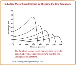
- If the voltage at the stator is changing linearly with frequency under base speed and remains constant at the rated value above base speed, then the resultant group of torque-speed characteristics is drawn in the given diagram. the rated speed for the motor is 1800 r/min.
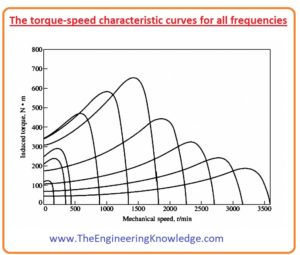
Disadvantage Motor Speed Control by Changing the Line Frequency
- Some years ago, the main drawback was that there was a need for special generator or mechanical frequency changer to change the frequency of the supply.
- This problem has disappeared with the development of modern solid-state variable-frequency motor drives.
- In fact, the frequency variation with solid-state motor drives has become a necessary method for speed control by frequency changing.
- The main point you should keep in mind is that this method can apply to every induction motor to control the speed but the pole changing method was not applicable to any motor without special stator wingdings.
Induction Motor Speed Control by Changing the Line Voltage
- The torque induced in the induction motor is directly proportional to the square of the applied voltage.
- If the load at the induction motor shaft has the torque-speed characteristic like which is shown in the given diagram, then the speed of the induction motor can be regulated (controlled) under a certain limit by changing the voltage of the line.
- Speed control by line voltage changing method is used for the small motor like fan motor.
Induction Motor Speed Control by Changing the Rotor Resistance
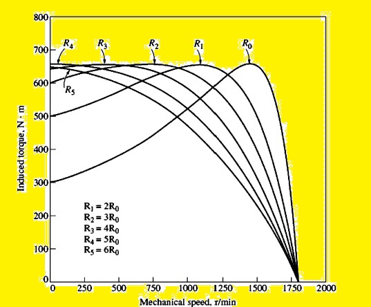
- In the case of the wound rotor induction motor, it is likely to vary the figure of the torque-speed curve by adding additional resistors in the rotor circuitry of the induction motor.
- After the addition of resistor in rotor circuitry, the new torque-speed characteristic curve is shown in the given diagram.
- If we have the torque-speed curve of the load of the motor like shown in the given diagram, then variation in the resistance of the rotor will speed of the motor.
- But the addition of extra resistors in the circuit of the rotor will decrease the efficiency of the motor.
- This method of speed change is normally used for a short interval of time due to loss of efficacy of the motor.
You can also read some related articles to the induction motor. That is described here.
- Introduction to Induction Motor
- Introduction to Three Phase Induction Motor
- Equivalent Circuit Induction Motor
- Induction Motor Torque-Speed Characteristics
- Variations in Induction Motor Torque-Speed Characteristics
- Power and Torque in Induction Motors
- Induction Motor Design Classes
- speed Control Method of Induction Motors
It is a detailed and well-explained tutorial on the Speed Control Method of Induction Motors, I have mentioned each and everything related to the speed Control Method of Induction Motors. If you have any questions can ask in the comments. See you in the next tutorial, Solid State Induction Motor Drives.


