Hello, fellows. I hope all of you are having fun in your life. In today’s tutorial, we will have a look at the induction motor torque-speed characteristics. There are lots of parameters we should know about the induction motor, and some questions also come to mind. Like, what will happen with the torque if the load varies? At motor start, what amount of torque can the motor be provided? What will happen with the speed if load increases on the shaft of the motor? To know the answers to these questions and other similar questions, first we should know the relation between the speed, power, and torque of the motor.
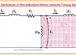
The torque-speed relationship of the induction motor will be inspected first from the variation of the field of the induction motor. Then, a universal equation for torque is calculated from the induction motor equivalent circuit, a circuit we have discussed in a detailed article. Today we will have a look at different parameters of the curve. So, let’s get started with the induction motor torque-speed characteristics.
Induction Motor Torque-Speed Characteristics
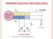
To find the torque-speed relation of the induction motor, we take a cage rotor of the induction motor, which is shown in the given diagram.
This rotor is working firstly without any load at its shaft, so its speed will be equal to the synchronous speed (nsync).
The net field (Bnet) in this motor will be generated by the magnetizing current (Im), which is described in the equivalent circuit of the induction motor.
The magnitude of the net magnetic field (Bnet) is directly proportional to the voltage (E1).
If the value of E1 is not changing, then the Bnet will also have a constant value.
In a real induction motor, (E1) fluctuates as the load varies, as the stator impedances (R1) and (X1) are the reason for variable voltage loss with changing load.
These losses in the windings of the stator part of the motor are comparatively minor, so E1 (as E1 is constant, so Im and Bnet will also be constant) almost remains constant with load variation.
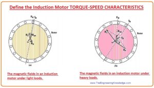
Torque of Induction Motor at no Load
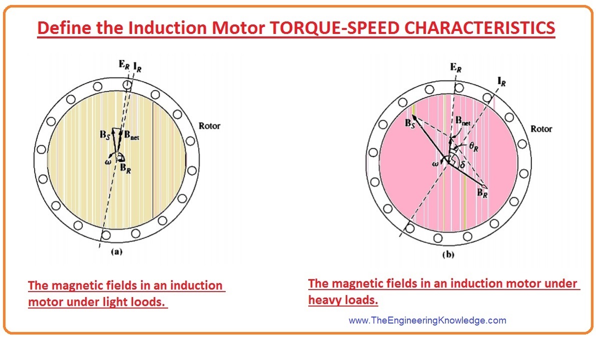
- We can see that in the figure that the motor has loaded at its shaft.

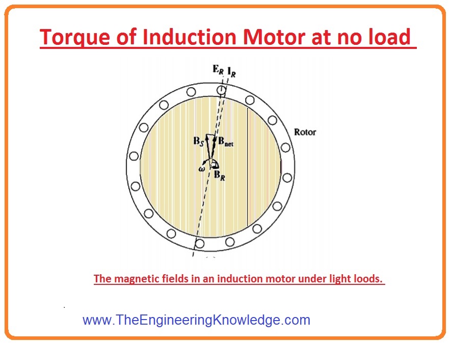
In a no-load condition, the value of slip (S) will be very low due to the comparative (relative) motion among the rotor and the stator fields being very low, and the frequency (f) of the rotor will also have less value.
As the relative motion is very little, the produced voltage (ER) in the rotor will also be little, and the current (IR) moving in the rotor will also have a low value.
Similarly, as the frequency of the rotor also low, the reactance (X) of the rotor is almost 0, and the rotor current (IR) will be in phase with the voltage of the rotor (ER).
The rotor current (IR) generates a small field (BR) at an angle somewhat larger than 90 degrees behind the (Bnet).
Note that the value of current at the stator should be larger even in the absence of a load; meanwhile, it should supply more than Bnet.
Due to this reason, an induction motor has a larger current at no-load conditions than other motors.
- The equation of torque at no-load condition can be given as.
Tind = KBR x BNET
- This equation can also have written as
Tind = KBR Bnet sins
- Subsequently, the field (B) of the rotor has a smaller value, so the induced torque will also be smaller (tind) just larger enough to overcome the rotating losses of the induction motor.
Torque of Induction Motor at Load
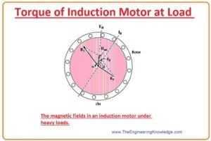
Let’s assume that the motor is connected with the load, as the load at the shaft of the motor varies (increases); the value of its slip (S) upsurges, and the speed of the rotor decreases.
As the speed of the rotor is lower, so is the relative (comparative) motion between the rotor and the static part (stator) field.
Due to larger comparative motion voltage induced (ER) in a rotor, it has a higher value, which generates a higher current in the rotor (IR).
As the rotor current increases, the field (BR) of the rotor will also increase. The angle between the current and the rotor field will also increase, which will decrease in case there is no load.
As the slip (S) of the rotor has a higher value due to this rotor frequency (fr = sfe), the increase in reactance (wLR) of the rotor will also increase.
Consequently, the current of the rotor (IR) now lags the voltage of the rotor, and the rotor field (BR) changes with the current (IR).
In the diagram, we can observe that the motor is working at a rather higher load.
Note that with the current increase, the angle also increased.
The increment in the BR causes an increment in the value of torque, but the angle increment causes a lessening of the torque.
As the 1st outcome is higher than the 2nd, the overall induced torque (tind) upsurges to provide the motor’s enlarged load.
When does an induction motor reach pullout torque?
The induction motor gets pull-out torque when the load on the motor’s shaft upsurges and the value of sin s decreases, then the increment in the value of the rotor field (BR).
At that condition, a greater increment in load reduces the induced torque (tind), and the motor halts or stops working.
It is likely to use information from the field of the motor to almost originate the output torque-vs-speed characteristic of an induction motor.
The value of induced torque is given as.
Tind = KBRBnetsins (s is the angle)
Explanation of Induced Torque Equation of Induction Motor
Tind = KBRBnetsins (s is the angle)
- Every component in this equation can be measured distinctly to study the complete performance of the motor.
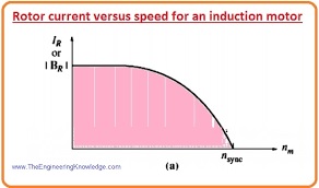
- BR, the field of the rotor of the motor, is directly proportional to the current moving in the rotor. The value of current moving in the rotor increases as the slip (s) increases. The current moving in the rotor is shown in the diagram.
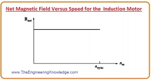
- The net Bnet field of the rotor is directly proportional to the (E1) so it is almost constant. The curve for Bnet, vs speed is drawn is given diagram.
- Since the angle (s) among the Bnet and rotor fields can be stated in a very valuable method. See diagram.
- In this picture, it is stated that the angle (S) is equivalent to the P.F (power factor) angle of the rotor plus (+) ninety degrees.
(S) angle = øR + 900
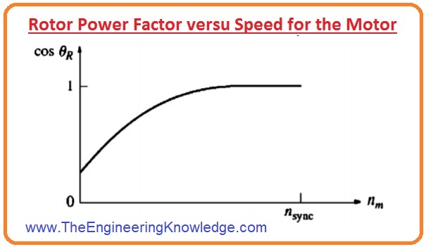
- So the sins = sin (øR + 900) = cosøR. This equation is the power factor (P.F) of the induction motor.
- The rotor (P.F) angle can be measured by the equation.
øR = tan-1 (XR/RR) = tan-1 (sXRO/RR)
- The subsequent P.F of the rotor is given as.
PFR= cos(tan-1(sXRO/RR) )
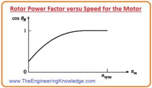
- A graph of rotor P.F vs speed is drawn in the figure.
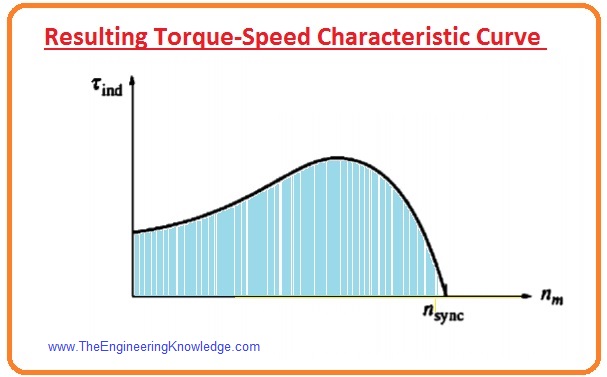
- As the torque induced (Tind) is proportionate to the product of the rotor field, net field, and power factor.
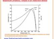
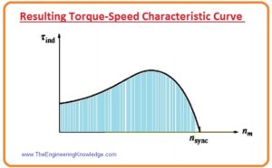
- The torque-speed characteristic of an induction motor is shown in the figure.
Regions of Torque-Speed Characteristic Curve of Induction Motor
- This representative curve can be separated into 3 areas.
First region
The first part is the less slip area of the curve. In this portion, the motor’s slip (s) upsurges almost linearly with the increment in the load, and the rotor mechanical speed reduces almost linearly with load.
In this area of the process, the reactance of the rotor is insignificant, so the rotor P.F. is almost one, whereas the rotor current (IR) upsurges with slip(s).
Second region
The 2nd portion on the curve of the motor is named the moderate slip (s) region.
In this portion, the frequency of the rotor is larger than earlier, and the reactance of the rotor is similar to the rotor resistance (RR).
In this part, the rotor current (IR) does not surge as quickly as earlier, and the P.F. starts to decrease.
Third region
This region of the induction motor curve is known as the higher slip portion. In this portion, the value of induced torque (tind) lessens as load upsurges.
Meanwhile, the upsurge in rotor current (IR) is entirely dominated by the reduction in rotor P.F.
For a distinctive induction motor, the pull-out torque on the curve will be TWO hundred percent of the evaluated torque at full load of the motor, and the starting torque of the motor will be one hundred fifty percent.
It is a detailed article on the Induction Motor Torque-Speed Characteristics I have explained every point related to an induction motor. If you have any issue you can ask in the comments. See your next tutorial, Variations in Induction Motor Torque-Speed Characteristics.
You can also read some related articles to the induction motor. That is described here.
- Introduction to Induction Motor
- Introduction to Three Phase Induction Motor
- Equivalent Circuit Induction Motor
- Induction Motor Torque-Speed Characteristics
- Variations in Induction Motor Torque-Speed Characteristics
- Power and Torque in Induction Motors
- Induction Motor Classes
- Induction Motor Design Classes