 Hello friends, I hope all of you are doing great. In today’s tutorial, we are gonna have a look at What is the No-Load Test of Induction Motor. The efficiency of higher power motors can be calculated by measuring their input and output or putting a load on them. In case of larger motor not easy to manage load. In loading experiments on the motors, the power loss will be higher. To decrease these power losses no-load and rotor locked test is done on the motors.
From the no-load test name, we can understand that this test is done in the absence of load on the motor, in this case, motor work at the synchronous speed. This test also has a resemblance to the open circuit test of the transformer. The other name of this test is running light. In today’s post, we will have a look at its circuit, working, summery and another factor. So, let’s get started with the What is the No-Load Test of Induction Motor.
What is the No-Load Test of Induction Motor
- The no-load test of the induction motor calculates the rotational (these losses are such power loss which occurs due to friction and windage) losses of motor and deliver knowledge about the magnetization current of the motor.
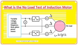
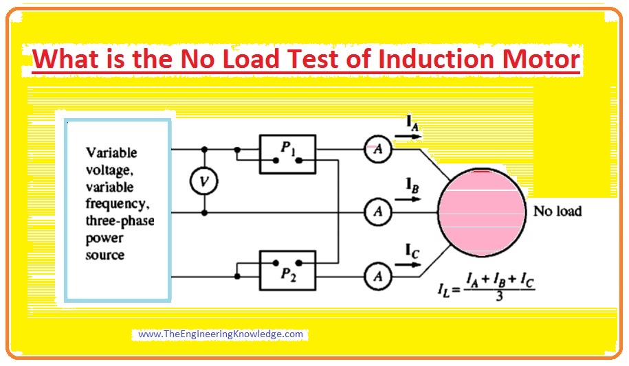
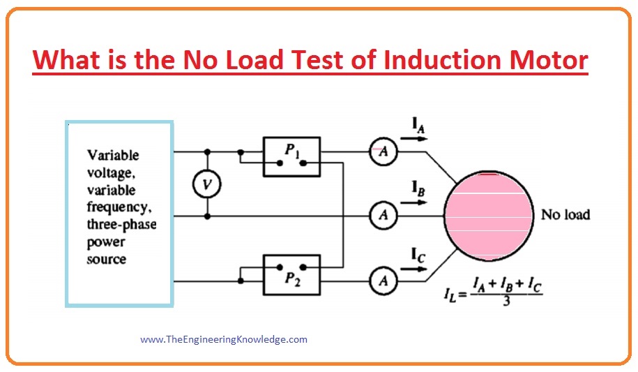
- The circuit for the no-load test is shown in the given diagram. In this circuit you can see that there are 3 amperemeters, a voltmeter and one power meter is connected with the induction motor.
- The load on this motor is just friction and windage losses which are also called rotational losses, so the all power supplied to the motor will convert to mechanical power and the motor has very less value of slip almost (0.001).
Working of No-Load Test of Induction Motor
- In a given diagram, you can see the equivalent circuitry of the induction motor.
- This circuit has a very small value of slip, With its very small slip, the resistance correspondent to its power transformed, R2 (1-s)/s has higher values than the resistance correspondent to the rotor copper losses (PRCL) R2 and higher than the reactance of rotor (X2).
- Due to these conditions, the equivalent circuitry of the motor will change two given circuitries which are mentioned as B, and C in the given diagram.
- You can see from the third circuitry which is denoted as C that the resistance of output is parallel to the output resistor is in parallel with the magnetization reactance (XM) and the losses in the core RC.
- This motor should have the input power equal to the losses at the rotor at no-load conditions.
- The PRCL is very minute since the current (I2) is very small so these losses can be ignored.
- The stator copper losses (PRCL) are given as.
PSCL = 3I21R1
- So, the input power of this motor will be.
Pin = PSCL + Pcore + PF&W + Pmisc
Pin= 3I21R1+ Prot
- Where Prot are the rotational losses of the induction motor.
Prot= Pcore + PF&W + Pmisc
- The corresponding circuitry which defines the motor working in this condition contains resistance (RC) and R2(1-s)/s in parallel with the magnetizing reactance XM.
- The current desired to create a field is larger in an induction motor, due to the higher reluctance of its air-gap, so the reactance (XM) will be lesser than the resistors in parallel with it and the overall input P.F will be very less.
- With the larger lag current, most part of the voltage loss will be across the inductive elements in the circuitry.
- The corresponding input impedance is consequently almost.
Zeq =(Vø/I) = X1+ XM
You can also read some related articles to the induction motor. That is described here.
- Introduction to Induction Motor
- Introduction to Three Phase Induction Motor
- Equivalent Circuit Induction Motor
- Induction Motor Torque-Speed Characteristics
- Variations in Induction Motor Torque-Speed Characteristics
- Power and Torque in Induction Motors
- Induction Motor Design Classes
- speed Control Method of Induction Motors
- Induction Motor Design
This the complete article about the No-Load Test of Induction Motor, each and every parameter related to this article is mentioned in this tutorial. You can further ask in comments. Thanks for reading. Take care until the next tutorial, Induction Motor DC test for Stator Resistance and Locked Rotor Test.


Nice article