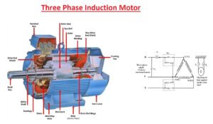
 Hello friends, I hope all of you are doing great. In today’s tutorial, we are gonna have a look at Introduction to Three Phase Induction Motor. A three-phase induction motor is a type of machine which mostly used in industries. There are 2 foremost kinds of three-phase induction motors first one is the squirrel cage and the other is the wound rotor motor. The squirrel cage motor is generally used in our households and industries because it is the cheapest, easy to repair and consistent. Induction motor is available in FHP (fractional horse-power are such motor whose output power is 746 or less it) to multiple megawatt range. FHP motors exist in single and polyphase such as three phases. The 3-phase motors are used in such submissions where higher torque is essential.
An induction motor is a kind of AC motor in which power is transferred to the rotor by the phenomena of Faraday law of electromagnetic induction. The induction motor turns (rotates) due to the force between the stator and the rotor’s magnetic field. The current at the stator produces a field that interacts with the field of the rotor and torque is induced in the rotor due to which it rotates in this way electrical energy is converted into mechanical energy. In today’s post, we will have a look at three-phase induction motor construction, working, slip, torque, and other parameters. So, get lets started with the Introduction to three-phase Induction Motor
Introduction to Three Phase Induction Motor
- A 3-phase induction motor is a machine which is constructed to work on the 3-phase supply.
- The three-ø induction motor is also known as the asynchronous. Its working is depending on the principle of the revolving magnetic field.
- As we discussed in a single-phase induction motor article that it is not self-starting, but three-phase motors are self-starting device there is no need of any separate starter for this motor.
- There are two main types of this motor which are with respect to rotor construction first one is the wound rotor motor and the second is the squirrel cage rotor.
- The construction of this motor is very modest, rugged, less cost and its repair is very easy, and this motor is available in many power ratings.
- This motor works at a constant speed in case of no load or full load conditions
Development of Induced Torque in a Three Phase Induction Motor
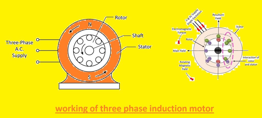
- In a given diagram we can see the cage rotor of three-phase induction motor.
- At this rotor, we have supplied 3-phase inputs at stating part of the motor and we can see that 3-currents moving in the stator.
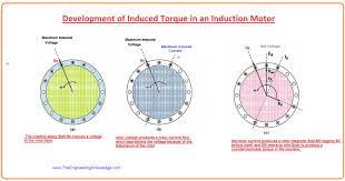
- These 3 currents create a rotating magnetic field (Bs) which revolves in an anticlockwise direction.
- The speed of this rotating magnetic field can be measured by the given formula.
nsync =120fe/p
- In this equation.
- nsync shows the speed of the rotating magnetic field.
- fe is the frequency of the system.
- (P) is no of the pole in the motor.
- The revolving field (Bs) when linked with the rotor then it induce emf in the rotor which is explained as.
eind= (v x B) x I
- In this equation:
- V is the rotation of the rotor with respect to the field.
- B is the rotating magnetic field.
- L is the length of the rotor (we can say that it is the length of bars in the field).
- It is the comparative motion of the rotor associated with the magnetic field which induces a voltage on the bars of the rotor.
- The direction of the Speed of rotor bars which are located on top is ninety degrees to the magnetic field which generates emf in these bars out of the page, but in lower bars, the direction of emf is induced in the page.
- However, as the rotor assemblage has inductive properties, the highest rotor current (I) lags the highest rotor voltage (V).
- The current moving in the rotor generates a rotor magnetic field which is denoted as BR.
Tind = kBR x Bs
- It is the induced torque in the motor.
- The resultant torque is in an anticlockwise direction. The rotation direction of the rotor depends on the direction of induced torque, as the torque direction is anticlockwise, so the rotor also moves in an anticlockwise direction.
- There is a fixed higher limit to the speed of a motor, but. If the rotor of the motor is moving on a synchronous speed, so bars of the rotor would be static with respect to the field and there will be no emf induced in the rotor.
- If induced emf is zero, then there will be no current in the rotor and no field.
Tind = kBR x Bs
- In this above equation, we can see that torque also depends on the rotor’s emf if there is no rotor emf then there will be no torque, so the motor will slow down and stop working.
What is Rotor Slip
- The induced emf in the rotor depends on the speed of rotation of the rotor with respect to the rotating field.
- Meanwhile, the operation of an induction motor relies on the voltage (V) and current (I), it is reasonable to dialogue about this comparative speed.
- 3 parameters are usually used to describe the comparative motion of the rotor and the magnetic fields (B).
- The first one is slip speed (nslip), it explains the difference between synchronous speed (nsyn) and rotor speed (nm).
- Slip speed described by the given formula as:
(nslip) = (nsyn)- (nm)
- In this equation:
- (nslip) denoted as the slip speed.
- (nsyn) describes the synchronous speed.
- (nm) is the speed of rotor rotation.
- The factor to describes the relative motion among the rotor speed and magnetic field is a slip.
- It is defined as the comparative speed articulated on a percentage basis. It can be defined by the given formula.
S = (nslip/nsync)x 100%
- If we put slip speed (nslip) in this equation that it becomes.
S = (nsync -nm)/(nsync) x 100%
- This equation can also be defined in terms of angular velocity.
s= (Wsync -Wm)/(Wsync)
- From this equation, we can see that if the rotor is moving on a synchronous speed then the value of slip is zero, and if the rotor is in stationery condition then the slip value is one.
Electrical Frequency on the Rotor of Induction motor
- The induction motor operates by the emf induced in the rotor, for this cause it also named as the rotating transformer.
- As in transformer primary winding induces voltage in the secondary winding, in the case of induction motor stator act as primary winding and rotor as the secondary winding.
- In the transformer, the frequency of the secondary remains the same but in the case of the motor frequency not remains the same.
- If we lock the rotor of the motor, then its frequency will become equal to the stator.
- If the rotor is revolving at the synchronous speed, then the frequency of the rotor will be 0.
- By the given formula, we can find the value of rotor frequency.
fr = (P/120) x ((nsyn)- (nm))
- In the equation:
- fr is represented as the rotor frequency.
- (nsyn) is the synchronous speed.
- (nm) is the speed of the rotor.
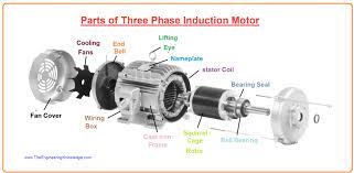
Parts of Three Phase Induction Motor
- There are mainly two parts of the three-phase induction motor first one is the stator of the induction motor and the second one is the rotor.
- These are the most important parts because both causes flux in the motor and its operation.
- Let’s discuss both in detailed.
Stator of Three Phase Induction Motor
- The stator of 3-ø induction motor is created by the combination of the large no of holes (slots) for insertion the three-ø wingdings circuitry, where three-ø input supply is provided.
- The 3-phase winding is designed in such a way that when the input supply provided on their terminals they produce a revolving magnetic field.
Rotor of Three Phase Induction Motor
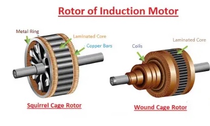
- The rotor of 3-ø induction motor comprises a cylinder-shaped coated core with corresponding slots (slots) that can have conducting wires.
- These conducting wires can be of copper (cu) or aluminum (Al) fixed in every slit (slot) and they are connected with the slip rings at the end.
- The slots on the rotor are not accurately created equivalent to the axis of the shaft but are positioned a slight tilted as this arrangement decreases magnetic buzzing sound and can avoid filibustering of the motor.
Working of Three Phase Induction Motor
- The stating part of the motor comprises of superimposing 3 windings which are designed at an angle of one-twenty-degree to each other.
- When the stator is linked to the three-ø alternating current supply it creates a revolving magnetic field that rotates at the synchronous speed.
- According to Faraday’s law, a voltage produced in any circuit is the cause of the rate of alteration of magnetic flux association through the circuitry.
- As we discussed the bars of the rotor are connected with slip rings when the revolving field of the stator interacts with the rotor this field generates an induced voltage in the rotor. Due to this, voltage is induced in the rotor.
- The comparative speed among the revolving flux and stationary rotor conductive wire is the source of current production.
- Therefore, from the operating principle of 3-ø induction motor, it can be detected that the speed of the rotor must not equal the synchronous speed produced by the stating part of the rotor.
- If the speed of the rotor is equal to the speed of the stator field then there will be no comparative speed, due to this there will be no voltage in the rotor of the motor, if there is no induced voltage in the rotor then there will no current flow in the rotor.
- Due to no current, there will be no torque in the motor and the motor will not work.
Features of Three Phase Induction Motor
- Three-phase induction motor is self-starting there is no need of special starter for this motor.
- This motor does not have brushes which cause to remove the sparking of the motor.
- This motor is Vigorous in structure.
- It is a less expensive motor.
- The repairing of this motor is very easy due to this feature is mostly used.
Applications of Three Phase Induction Motor
- This motor is used in elevators.
- Three-phase induction motor is used in Cranes.
- This motor is also used in Huge volume exhaust fans.
- It used in Engine Supplementary propels.
- It works as the Engine blower fan motor.
Advantages of Induction Motor
- These motors are vigorous and modest in structure with very limited moving portions.
- These motors proficiently work in a rough and strict atmosphere like in oceangoing containers.
- The repairing price of the three-ø induction motor is fewer and dissimilar that of direct current or synchronous motor, the induction motor does not have the brush, and slip rings.
- It can operate in an inherent atmosphere as they do not have brushes which can source the sparking and can be hazardous to such an environment.
- Three-ø induction motor does not need any extra starting device or arrangement as they can produce starting torque when 3-ø alternating voltage is provided.
- The ultimate results of a 3-ø motor are approximately (1.5) times the rating of a 1-ø motor of the identical ratings.
Disadvantages of 3 phase Induction motor
- In its starting process, it takes the higher preliminary initial current when connected to a weighty load.
- It sources a loss in voltage at the starting time of the motor.
- The induction motor works at lagging P.F which consequences in an increment of the (I2R) losses and decreases efficiency, particularly at light load. To recover the P.F stationary capacitor banks are used with the motor.
- The speed controller of the 3-ø induction motor is challenging as associated with direct current motors. An adjustable frequency driver can be combined with the induction motor for speed regulation.
It is all about the three-phase induction motor, I try my level best to explain each and everything related to the three-phase induction motor. If you have any query ask in comments. I hope you enjoyed this tutorial. Thanks for reading. see you in the next tutorial, about an induction motor. Have a good day.
You can also read some related articles to the induction motor. That is described here.
- Introduction to Induction Motor
- Introduction to Three Phase Induction Motor
- Equivalent Circuit Induction Motor
- Induction Motor Torque-Speed Characteristics
- Variations in Induction Motor Torque-Speed Characteristics
- Power and Torque in Induction Motors
- Induction Motor Design Classes
- Maximum Pullout torque of Induction Motor
- Induction Motor Design




well explained
Hello. This post was extremely interesting, especially because I was looking for ideas on this topic last Thursday.
King regards,
Boswell Henneberg
Thanks for share this article it’s quite helpful to me.
Best regards,
Balle Griffin
At last, I discovered an article that I am searching for quite a long time.
I hope it will help me .
Best regards,
Mead Schneider
I know this if off topic but I’m looking into starting my own blog and was curious what all is needed to get set up? I’m assuming having a blog like yours would cost a pretty penny? I’m not very internet smart so I’m not 100 positive. Any suggestions or advice would be greatly appreciated. Kudos
Hi there very nice website!! Guy .. Beautiful .. Superb .. I’ll bookmark your web site and take the feeds also…I’m satisfied to find so many helpful information here within the put up, we need develop extra techniques in this regard, thanks for sharing. . . . . .
Thank you so much. At last, I found anarticle thath I am
searching for quite a long time. I hope that it
will help me also.
Best regards,
Lunding Henneberg
I like the helpful information you provide in your
articles. I will bookmark your weblog and check again here regularly.
I’m quite certain I will learn many new stuff right here!
Best of luck for the next!