 Hello friends, I hope all of you are doing great. In today’s tutorial, we are gonna have a look at the Induction Motor DC test for Stator Resistance and Locked Rotor Test. The rotor resistor (R2) plays a very important character in the working of the induction motor. It also assists in finding the torque-speed curve design and calculating the speed at which the maximum (pullout) torque will exit. To measure the total resistance that exists in the motor circuit locked rotor test is done on the motor. This test computes the entire resistance value of the circuitry.
To calculate the resistance (R2) of the rotor we should have the idea of R1 (stator resistance) so that it can subtract from the total resistance. The test is done on the motor to find the resistance (R1) of the stator is named as dc test of the induction motor. In today’s we post will have a look at the working, equation, circuit, and other parameters of these two tests. So, let’s get started with an Induction Motor DC test for Stator Resistance and Locked Rotor Test.
Induction Motor DC test for Stator Resistance
- In the DC test of Induction Motor, dc supply is given at the stator of induction motor. As input is DC there will be no induced voltage in the rotor and no current will move in the DC. The reactance (Xr) of the motor will also ‘0’ at DC.
- So, the only element which is restring the current in the motor is the resistance of the stator and it can be calculated by the DC test.
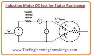
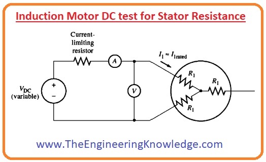
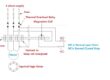
- The circuit diagram for the DC test is shown in the given diagram.
- You can see that in this circuit the motor has a Y connection circuit and two terminals of this connection are linked with the DC supply.
- To do the test, the current at the stator is set to the rated value, then the voltage is measured by the voltage meter which is connected.
- The current at stator is set to the rated value to get the same heating condition that the motor has during its normal working.
- As we know the two terminals of stator windings are connected with the DC input so the current moves through 2 windings, due to this the total resistance in the path of the current will be (2R1). Which is given here.
2R1=VDC/IDC
R1= VDC/2IDC
- By finding the value of R1 the stator losses at the stator can be measured and the Prot losses can be calculated by eliminating stator losses from the input power (PIN).
What is the Locked Rotor Test of Induction Motor
- There is another test that is performed on the motor to know the different constraints of the motor locked rotor test is also known as the block rotor test.
- In this motor the rotor is static and input supply is given to the motor and the corresponding current, the voltage measured according to the supply.
- The lock rotor test is also like the short circuitry test of the induction motor.
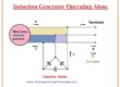
- You can see the circuit diagram of the Locked Rotor test. During this test, we will apply the AC voltage at the stator of the motor and set the current at full load value.
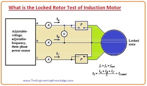
- After setting the current at the full load value the motor parameters like current-voltage and power are computed.
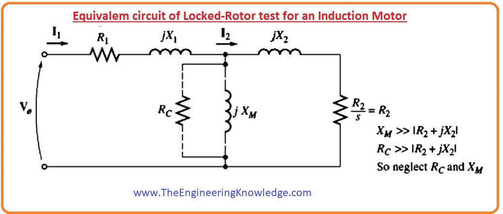
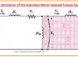
- The corresponding circuit for this test is drawn in given a diagram.

- You can see that as the rotor is not moving, hence the value of slip will be one.
- So, the rotor resistance whose formula is R2/s will become R2 (has a very less value) as the slip value is one.
- As the values of R2 and X2 are very less so the total input current will pass by these two parameters, in its place to move by higher magnetize reactance (XM).
- So the circuitry of the motor in these situations behaves like a series circuit that has X1, R1, X2, and R2.
The problem of the Locked Rotor test of the induction Motor
- There is an issue that we must face during this test.
- During normal working, the frequency at the stator will be smaller as the input supply frequency which is fifty of sixty hertz.
- At initial situations, the frequency of the rotor will also have the same value as the input supply frequency has.
- Nevertheless, at usual working situations, the motor has slip (s) almost two to four percent, and the resultant rotor frequency is in the range of one to three hertz.
- It creates a problem in that the input supply frequency does not signify the normal situation of the rotor.
- Meanwhile resistive of the rotor is the main function of frequency for class B and C motor the improper rotor frequency can cause disturbing findings of this test.
- Characteristic cooperation is to use a frequency of twenty-five % or less than the rated frequency.
- Whereas this tactic is suitable for fundamentally constant resistance rotor structures like class A and D, it left a lot to be anticipated (desired) when one is working to find the normal rotor resistor value of a variable-resistance rotor.
- Since these and similar difficulties, a great deal of care should be taken in during these tests.
Equation of Locked Rotor test of induction Motor
- After setting the test frequency and voltage, the current moving in the motor will rapidly reach the rated value, and the input power (Pin), voltage (V), and current (I) are calculated before the rotor becomes hot (heat up).
- The input power of the motor is given as.
Pin=√3VTILcosø
- The blocked rotor P.F can be calculated by this equation.
PF= cosø= Pin/√3VTIL
- The magnitude of the total impedance in the motor circuitry is given as.
ZLR=Vø/I1 =VT/√3IL
- The angle of total impedance is given as.
ZLR=RLR+jX’LR
= ZLRcosø +j(ZLR)sinø
- Hence the resistance of the locked rotor is
RLR =R1+ R2
- And the reactance of a locked rotor will be.
X’LR=X’1 + X’2
- In this equation, the X’1, and the X’2 are the rotor and stator reactance at the testing frequency.
- The resistance of the rotor can also write as.
R2=RLR-R1
- In this equation, R1 is the value of stator resistance which we calculate during the DC test.
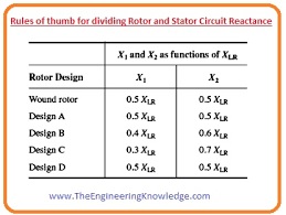
- The entire rotor reactance (Xr) mentioned to the stator can also be calculated. As the reactance (X) is directly proportionate to the frequency (f), the total corresponding reactance at the nominal working frequency can be calculated by this formula.
XLR=frated/ftestX’LR= X1+X2
- Inappropriately, there is no simplest method to isolate the dependency of the stator and rotor reactances from each other.
- Over the ages, understanding has revealed that motors of specific design categories have specific relation amid the rotor and stator reactances.
- The given diagram explains the relationship between these two reactances.
stator resistance formula
We can measure stator resistance with of multimeter in DC mode and formal for stator resistance Rs=U/I. We can measure Stator Induction by Stator Current measurement in Free Run mode:
X=U/I; Ls=X/(2 x Pi x f
rotor resistance formula
As the winding of the rotor is created with copper or aluminum conductors. It comes with definite resistance (R= ρl/a). it is a constant value and is shown as R2.
So that all about the Induction Motor DC test for Stator Resistance and Locked Rotor Test, if you want to know something else about these tests or edit something you can comment below. See you in the next tutorial, single-phase induction motor.
Faqs
- This test is known as the dc resistance test, the dc voltage is provided at the stator windings of the induction motor. Since the current is dc there is not induced voltage in the rotor circuit and not rotor current. The reactance of motor is zero for direct current.
What is the purpose of locked rotor test in induction motor?
- The blocked rotor test is done on the induction motor to find leakage impedance. With that torque, motor, short-circuit current at normal voltage, and can also be found.
- Rotor resistance starter used in high rating slip ring induction motor. it uses external resistance in the rotor circuit so the rotor produces high torque. High torque is generated at low speeds if external resistance has high value.
- In a locked rotor test voltage is provided at stator terminals are less for avoiding damage to stator winding. Low voltage is used to stop the rotor from rotating, make it zero, and provide full load current through stator winding. For slip at unity, load resistance is zero.
- Winding resistance is found by measuring voltage and current in the motor. The resistance is measured with ohm law, that defines that resistance is equal to voltage divided with current.
You can also read some related articles to the induction motor. That is described here.
- Introduction to Induction Motor
- Introduction to Three Phase Induction Motor
- Equivalent Circuit Induction Motor
- Induction Motor Torque-Speed Characteristics
- Variations in Induction Motor Torque-Speed Characteristics
- Power and Torque in Induction Motors
- Induction Motor Design Classes
- speed Control Method of Induction Motors
- Induction Motor Design
- No-load Test of Induction Motor
- Solid State Drive Induction Motor


Could you maybe specify what will be the effect of AC on the DC resistance measured in the stator resistance test? And also how to take it into account when modelling it.