 Hello friends, I hope all of you are fine. In today’s tutorial, we are gonna have a look at Synchronous Generator Operating Alone. The performance of the synchronous generator with different load relies on the P.F of the load and the at its working conditions either it is working separately or with some other generator. There are many factors that affect the working of the synchronous generator.
In today’s post to see the operation of the synchronous generator, we will construct a phasor diagram and will observe the effect of the armature resistance RA. so let’s get started with the Synchronous Generator Operating Alone.
Effect of Load Changes on a Synchronous Generator Operating Alone
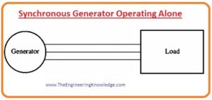
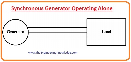
- To study the features of the generator when it is working alone we connect the load with it.
- A given diagram shows the load connected with the generator.
- If we increase the connected load, then there will be automatically incremented in the active power (P) or reactive (Q) of the generator.
- By increment in the load also increases the value of current that used by the load celled load current (IL).
- As the field windings resistance is not varied, so field current also has same value due to these two constants the flux generated by the field current also constant.
- Subsequently, the prime mover also moving the rotor of the generator with the same velocity.
- As the field current, flux, and field resistance all are constant, so the internal generated voltage EA will also constant.
EA= Køw
- As the internal generated voltage is constant, if we vary the load and find the effect of the variation in the load we will draw different loads phasors diagram and discuss them.
- To study variation effect of the load we connect three different loads inductive, capacitive and resistive. Then see their results by phasor diagrams.
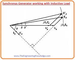
Synchronous Generator working with Inductive load
- As the generator is connected with the inductive load its power factor will be lagging.
- If we increase the amount of the load connected at similar P.F, due to increment in the load the armature current also increases, but its angle ø with the terminal voltage Vø has similar value as before changing.
- So, the armature reaction voltage jXsIA also increases but still has a similar angle as before load increment.
EA = Vø + jXsIA
- jXsIA must draw amid Vø and EA at an angle of zero degrees, it is the factor that has the same value as before load variation.
- If we make a phasor diagram among the Vø, EA, and jXsIA, so we can observe that there is one point at jXsIA that can be parallel to its previous position as before load increment.
- The resultant phasor diagram is shown here.
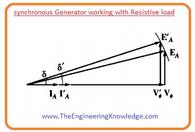
Synchronous Generator working with Resistive Load
- Now if we connect the resistive load with the generator, from the given phasor diagram we can observe that the value of the terminal or phase Vø will decreases.
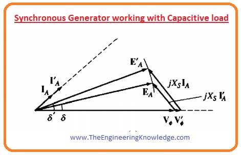
Generator working with Capacitive load
- Let’s suppose now the load connected with the generator is capacitive. The value of the phase voltage will increase this time. You can see the capacitive load effect in a given figure.
- By analyzing the effect of the three loads on the generator we conclude three facts that are described here.
- If we connect inductive load with the synchronous generator Vø and terminal voltage Vt will decrease largely.
- In the case of the resistive load, there will slightly decrease in the Vø and terminal voltage Vt.
- If the load is capacitive then the Vø and terminal voltage Vt will increase.
Voltage Regulation of the Synchronous Generator
- We can very easily compare the voltage performance of the 2 generators by their voltage regulation.
- The formula of the voltage regulation is given here.
VR = [(Vnl – Vfl)/ Vfl] x 100%
- In this equation, Vnl is the no-load voltage of the generator and the Vfl is the rated voltage of the generator.
- If the synchronous generator is connected with the inductive load its voltage regulations are highly positive.
- If the load is resistive then the voltage regulation is less positive.
- If the load is capacitive then the voltage regulation is negative.
- Usually, it is necessary to maintain the voltage level provided to the load, either load itself is changing or not.
- To keep voltage constant changes the internal generated voltage if the load is changing.
- As we know.
EA= Køw
- As the speed is constant so we can control internal generated voltage by speed changing, an option is to vary the flux of the rotor.
- Let’s take an example, let’s assume that the inductive load is connected to the generator. As we have discussed above terminal voltage will decrease with the increase of the inductive load.
- To again maintain the voltage to the last value, decrease the field resistance.
- The decrement in the field resistance will increase the field current, which increases the flux.
- Flux increment will increase the internally generated voltage EA, which will increase the phase voltage and the terminal voltage.
Synchronous Generator Operating Alone Summary
- We can summarize this explanation as.
- The decrement in the field resistance will increase the value of the field current.
- An increment in the field current will increase the flux.
- Flux increment will increase the internally generated voltage EA.
- An increment in the internally generated voltage will increase the phase voltage.
- If you have to decrease the terminal voltage, then do all the steps from last to first. It is very easy to maintain the terminal voltage with the change in the load by just controlling the field current.
Faqs
What is the operation of a synchronous generator?
- The synchronous generator is type of generator that works at a synchronous speed defined through frequency of the connected grid, irrespective of the magnitude of torque applied. The field in this generator is made by using permanent magnets or through conventional field winding.
Why are synchronous generators operated in parallel?
- Generators in parallel combination help one or more to be removed for shutdown and maintenance. If there is a single generator in the system it not operate at full load and not be effective.
What are the operating modes of a synchronous generator?
- There are two modes of synchronous machines, generator mode and motor mode. In generator mode machine provide current and excitation voltage is higher than terminal voltage (V).
You can also read some related topics to synchronous generator that are listed here.
Introduction to Synchronous Generator
Synchronous Generator Equivalent Circuit
Synchronous Generator Phasor Diagram
Synchronous Generator Power and Torque
Synchronous Generator Parameters
Synchronous Generator Parallel Operation
Synchronous Generator parallel with Large Power system
Synchronous Generator Parallel with same Size Generator
Synchronous Generator Capability Curves
Synchronous Generator Transients
That’s all about Synchronous Generator Operating Alone if you have any question about it ask in comments. See you next tutorial Parallel Operation of Synchronous Generator.