 Hi friends, I hope all of you are fine. In today’s tutorial, we are gonna have a look at the Equivalent Circuit of Synchronous Generator and how it describes the different parameters of synchronous generator. As we know that there are 2 fields exists in the synchronous generator first one is the rotor field and the other one is stator. The field at the rotor produces the rotating magnetic field at the stator or armature windings. The voltage induced at the stator is also called internal generated voltage (EA).
Similarly, the current moving in stator windings (armature) also produces a voltage in the stator. In today’s post, we will relate these two voltages and study the effect on the generator, and construct the equivalent circuitry of the synchronous generator. So, let’s get started with what is the synchronous generator equivalent circuit
What is the synchronous generator equivalent circuit
- The voltage (EA) is the voltage produced at a single phase of the synchronous generator.
- But this is not the voltage that we get normally at the output points of the generator.
- The internal generated voltage (EA) can be equal to the phase voltage (Vø) when there is no armature current is moving through the generator.
- Some factors explain why the internally generated voltage is not like the phase voltage (Vø).
- The structure (shape) of the salient poles rotor.
- The self-inductance of the stator (armature) windings.
- The armature reaction.
- The resistance offered by the armature windings.
What is Armature Reaction
- We study that there are 4 main facts that affect the internally generated voltage of the synchronous generator. The armature reaction is the main factor that largely affects the voltage we discuss it with detail.
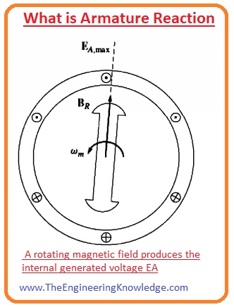
- When the rotor of the generator rotates, the field of the dc voltage at the rotor produces the voltage (EA) in the armature winding of the stator.
- If there is load connected with the output terminals of the generator, then the current will flow through the armature windings of the stator.
- This current will have its separate field, this field will interact with the field of the rotor and affect the internal generated voltage (EA). This phenomenon is called armature reaction.
- To study the armature reaction, you can see in the given diagram there is a rotor that has 2 poles and rotates in the 3-phase stator.
- At the stator, there is no load connected. The field of the rotor BR generates the EA internal voltage at the stator.
- As there is no load connected to the generator there will be no armature current and the EA will equal to the Vø.
- The given diagram shows the assembly of no-load rotor.
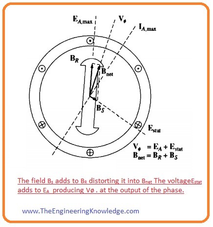
- If we connect the inductive load with the generator, the maximum current lags the maximum voltage. You can observe this fact from the figure.
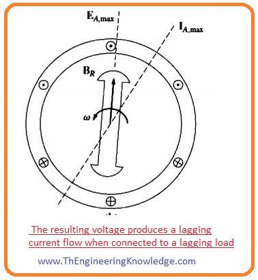
- The current passing through the stator windings will generate a field in the stator. It is denoted as BS and its direction can be fined by the right-hand rule and is shown in a given diagram
- The field of the stator (BS) will generate a voltage in the stator and this voltage is represented in the figure as Estat.
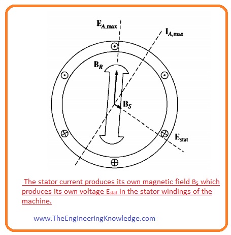
- As there are two voltages at the stator first is the internal generated voltage EA and other voltage due to armature reaction Estat.
- So, the total phase voltage at the terminals of the generator will the sum of these two voltages.
Vø = EA + Estat
- The total field at Bnet is the sum of the stator and the rotor fields.
Bnet =BR +Bs
- As the angles of the EA and BR are identical and the angles of the Ea and Bs are also similar. So, the resultant field (Bnet) will overlap with the total voltage at generator Vø.
- You can see the resultant voltages and currents in a given figure.
Equivalent Circuit of Synchronous Generator
- To understand the construction of an equivalent circuit of generator, first, we should keep in mind that stator voltage is Estat ninety-degree lag behind the peak current IA.
- 2nd thing is to keep in mind that the stator voltage Estat is directly proportionate to the armature current IA.
- Let’s suppose that ‘X’ is constant, then the voltage produced due to the armature reaction will be written as.
Estat = -jXIA
- The voltage at output terminal of the generator will be.
Vø = EA – jXIA
- See the given circuitry.
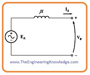
- If we apply kvl at this circuitry the value of voltage will be.
Vø = EA – jXIA
- This equation is like the equation that describes phase voltage of the generator.
- So, the voltage of the armature reaction can be displayed like an inductor in series with EA.
- The windings of the stator have some value of their self-resistance and reactance. If the resistance is denoted as RA and reactance XA then the difference between the internal generated voltage EA and phase voltage is given as.
Vø = EA – jXIA – JXAIA– RAIA
- The armature reaction and self-inductance of the generator are denoted as reactance’s, so these are written as single reactance and named as the synchronous reactance of the generator.
XS= X + XA
- So, the final equation for the phase voltage will be given as.
Vø= EA – jXsIA– RAIA
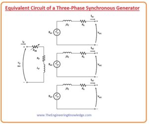
- The equivalent circuit diagram of synchronous generator, of the 3-phase synchronous generator is given here.
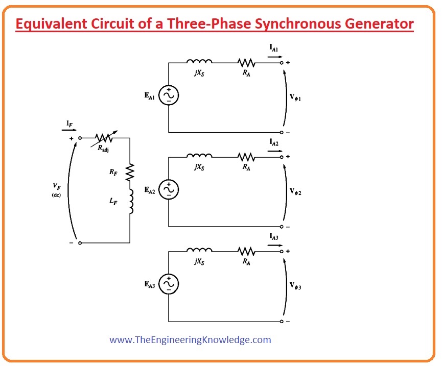
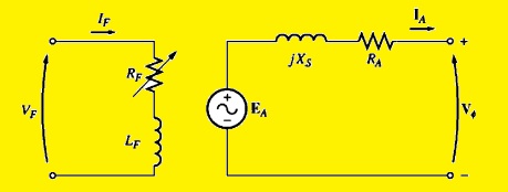
- You can see from the figure that the direct current power supply is connected with the field circuitry of the rotor.
- The field circuitry of the rotor is shown by an inductance of the winding and resistance in series.
- In field circuitry there is an Radj is a variable resistor that governs the field current.
- The other part of the circuitry has the circuits for the 3 phases of the stator.
- Every phase circuitry consists of the internally produced voltage EA and the synchronous reactance and armature resistance RA.
- All three phases have same magnitude but their current and voltage are one-twenty degrees out of phase from each other.
- The 3 phases of stator can be connected in the wye or delta form. These are shown in given circuitry.
- pic
- If the connections are wye then the output voltage of the generator will be.
VT = √3Vø
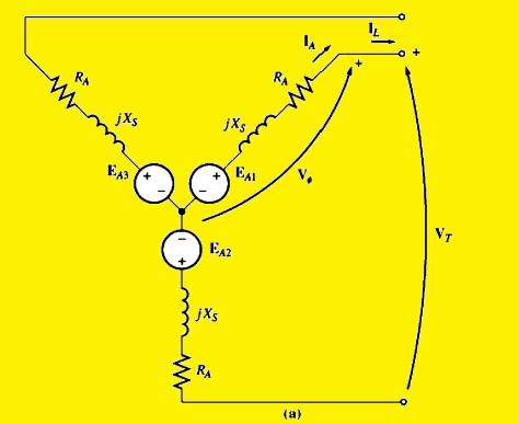
- in the generator equivalent circuit connection is delta then the output voltage will be.
VT = Vø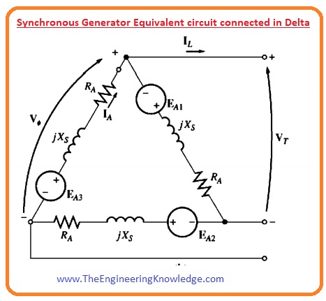
- As the 3 phases have same magnitude but different phase angle so the per-phase equivalent circuitry for a synchronous generator is shown below.
You can also read some related topics to synchronous generators that are listed here.
Faqs
- V is voltage per phase to motor, Rz is armature resistance per phase and Xs is synchronous reactance per phase. Ra and Rx provide synchronous impedance per phase Zs of motor
- The synchronous speed is Ns = 120f P here Ns is RPM, f frequency is HZ and P is the number of poles
- Synchronous generators are called alternators. The alternator word is used since it generates ac power. it is called a synchronous generator since it operates synchronously speed for generate AC power at the required frequency.
- Phasor diagram and equivalent circuits are used for the analysis of AC electrical machines, Different components of the phasor diagram for salient pole machine are made with the use of two reactions that were defined by A. Blondel in 1895.
- The synchronous generator works on Faraday laws of electromagnetic induction. Electromagnetic induction defines that EMF force is induced in an armature coil if it rotating in a uniform magnetic field.
- Synchronous motors transform electrical energy into mechanical energy. The generator converts mechanical energy into electrical energy.
- The equivalent circuit defines the theoretical circuit that comes with all the features of a given circuit. The equivalent circuit is the type that simplifies calculation easily.
Introduction to Synchronous Generator
Synchronous Generator Phasor Diagram
Synchronous Generator Power and Torque
Synchronous Generator Parameters
Synchronous Generator Operating Alone
Synchronous Generator Parallel Operation
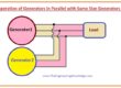
Synchronous Generator parallel with Large Power system
Synchronous Generator Parallel with same Size Generator
Synchronous Generator Capability Curves
Synchronous Generator Transients
That’s all about the generator equivalent circuit, synchronous generator if you have a query ask in comments thanks for reading. See you in the next tutorial Phasor Diagram of a Synchronous Generator
How to transfer my blog from blogspot to paid hosting?