 Hello friends, I hope all of you are fine. In today’s tutorial, we are gonna have a look at the Phasor Diagrams of a Synchronous Generator and how they describe the different parameters of a synchronous generator. The phasor diagram is a very significant factor of the power system analysis. As the output of the synchronous generator is alternating current, so it can easily be explained by the phasor diagrams. If we draw the output voltage and current in such a geometrical way that they show some relation among them, the resultant diagram is called a phasor diagram.
In the last tutorial, we discussed the synchronous generator equivalent circuit. If first, you read it then it will be easy to understand the phasor diagrams of the synchronous generator. In today’s post, we will have a look at different parameters related to phasor diagrams, and will learn how to make these diagrams. So, let’s get started with the phasor diagram of the synchronous generator.
Phasor Diagram of a Synchronous Generator
- In the electrical power system, there are three main types of load first one is resistive, the second one is capacitive and the third one is inductive.
- We will connect all three loads with the synchronous generator and will see their effect and draw their phasor diagram.
Phasor Diagram of a Synchronous Generator at Unity P.F
- The given diagram shows the relation among the parameters like phase voltage (Vø), internal generated voltage (EA), armature current (IA), synchronous reactance (XS) and some other factors by phasor diagram when the generator is working with the resistive load and have unity power factor.
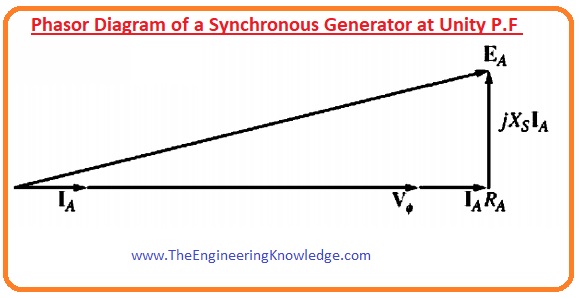
Vø= EA – jXsIA– RAIA
- We can observe from the above-given equation that internal generated voltage (EA) are will be equal to the phase or terminal voltage of the generator if we deduct the voltage loss due to armature resistance and the synchronous reactance from it.
- All these parameters and their facts are shown in the above-given diagram.
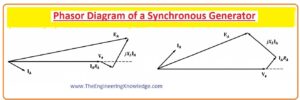
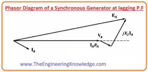
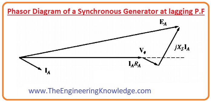
Phasor Diagram of a Synchronous Generator at lagging and leading P.F
- In a given diagram, we have construed the phasor diagram of the synchronous generator when it relates to the inductive load, in this case, the power factor will be lagging.
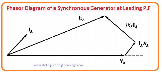
- There is also a phasor diagram of the synchronous generator when it connected with the capacitive load, in this case, the power factor will be leading.
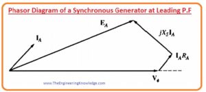
- If we compare the lagging and leading load phasor diagrams of the synchronous generator we can conclude that to get a specific value of the phase or terminal voltage and armature current we will require a larger amount of internal generated voltage EA for the inductive load (lagging) than the capacitive load (leading).
- So, we will have to provide a larger field current at the rotor in case of inductive load (lagging load) than the leading load to generate the same amount of the terminal voltage (Vø).
- As we know.
EA = Køw
- In this equation, EA is internally generated voltage.
- ‘K’ is constant.
- ‘∅’ is flux.
- ‘w’ is speed of rotation of the rotor.
- In this equation, ‘w’ should be non-variant to keep the frequency constant.
- For the given amount of field current at the rotor and current consumed by the load, the magnitude of the phase voltage (Vø) will be less for the inductive load and higher for the capacitive load.
- In all synchronous machines, whether it is a motor or a generator, the value of the synchronous reactance (Xs) is higher than the armature windings resistance (RA), so sometimes RA is ignored for quality observation of the voltage changing.
- But in the case of different mathematical problems, RA should be considered.
- In real synchronous machines, the synchronous reactance is normally much larger than the winding resistance RA, so RA is often neglected in the qualitative study of voltage variations. For accurate numerical results, RA must be considered.
Faqs
- The phasor diagram is used to show the relation between two or more sine waves with the same frequency. In the phasor diagram, phasors are denoted with open arrows and rotate anticlockwise with an angular frequency of ω for the origin.
- If a synchronous generator is connected to the supply network, its rotational speed is constant. This generator comes with a static stator and slots in stator windings, that is called armature windings and/or a rotating rotor.
- The synchronous generator is important for power production systems, transforming mechncal energy into electrical energy. It works on the principle of Faraday’s law of electromagnetic induction, where a conductor moves in a magnetic field and generates an electromotive force (EMF)
- Phasors are rotating vectors with lengths equal to the peak value of oscillations and angular speed equal to the angular frequency of oscillations. it is best to show the phase relation between two or more oscillations. it used to add/subtract oscillations
You can also read some related topics to synchronous generators that are listed here.
Introduction to Synchronous Generator
Synchronous Generator Equivalent Circuit
Synchronous Generator Power and Torque
Synchronous Generator Parameters
Synchronous Generator Operating Alone
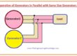
Synchronous Generator Parallel Operation
Synchronous Generator parallel with Large Power system
Synchronous Generator Parallel with same Size Generator
Synchronous Generator Capability Curves
Synchronous Generator Transients
This is the complete tutorial about phasor diagram of the synchronous generator if you have any queries ask in comments. See you in the next tutorial Power and Torque in Synchronous Generator. Have a good day.


Your home is valueble for me. Thanks!…