 Hello friends, I hope all of you are fine. In today’s tutorial, we are gonna have a look at Synchronous Generators in Parallel with Large Power Systems. The large power system comprises 2 or more bus bars that are linked with each other by the single or many power lines, the impedance of these power lines is less than the overall power but it cannot be ignored. But the system’s bus bar impedance (Z) can be ignored. This difference makes difficult to measure the current flowing in the system and voltage drop, then the voltage measurement of the generator that is connected with the common bus bar in the system.
In today’s post, we will relate these parameters of the power system and study the working of the synchronous generator when it is connected with the large power system. So, let’s get started with the Operation of Generators in Parallel with Large Power Systems.
Synchronous Generators in Parallel with Large Power Systems
- If a single synchronous generator is attached to the power generation network, there will be no effect of this generator in the total generation of the power system.
- The example of this is the united states power generation station, where if we installed a single generator there will be no effect of this generator in the overall frequency and power of the system if this generator is working or not.
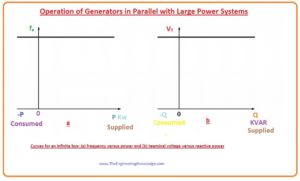
- We can compare this situation with the infinity bus bar system. An infinity bus is a larger power system whose voltage and frequency do not change irrespective of how much quantity of the active and reactive power is delivering to it or taking out from it.
- The relation among the active power and the frequency and the relation among the reactive power and the terminal voltage of this infinity bus is shown in given diagram.

Synchronous Generator Operating in Parallel with an Infinite Bus
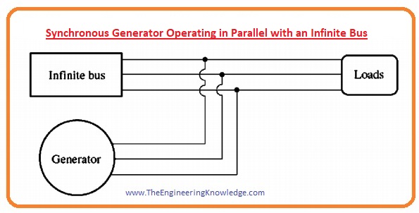
- For a practical understanding of the generator attached with larger power network, we study such network that has a synchronous generator connected with the infinity bus in parallel and delivering power to the load.
- Let’s suppose that the mechanical power source of generator that called prime mover is connected with the governor system (it controls the speed of the prime mover to decrease, in case of any variation in the load or high-power demand) and the field current is regulated by the variation in the resistance.
- lt is easy to discuss generator working without using an automatic field current controller, so we will not consider the automatic field regulator, the given diagram shows the system in which synchronous generator is connected with the infinity bus bar.
- When we connect a single synchronous generator with larger power network then the output voltage VT and the frequency of the generator and power system should remain equal, until we attach their output terminals.
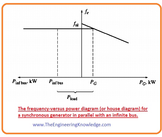
- So, the graphical representation of the frequency and active power and reactive power and terminal voltage can be constructed with the same y-axis. Such type of graphical representation that has a common vertical axis is known as house diagram. You can see it in a given diagram.
Frequency-Power Diagram of synchronous Generator after Paralleling
- Let’s suppose that the synchronous generator is connected in parallel combination with the infinity bus according to the Parallel Operation of Synchronous Generator
- Then the generator will start to provide active power to the load or small amount of the reactive power. The graphical representation is shown in a given diagram.
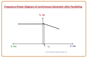
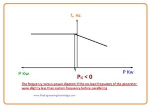
- Let’s assumes that the connected generator has less frequency than the infinity bus instead of having larger frequency that is the condition for parallel operation. The resulting curve of this situation is drawn in a given figure.
- You can see from the above figure that the frequency of the generator when there is no load connected with it is less than the frequency of the infinite bus or system.
- In this condition the output power of the generators is negative, it means when the frequency is less than the system’s frequency and it has no load then it works like a motor and uses power instead to deliver power to the load.
- Always make sure that the frequency of the incoming generator should be slightly larger than the frequency of the system. So that it works like generator not motor.
- Most of the generator have reverse power trip circuitry, it makes sure that the frequency of the generator should remain higher than the system.
- In some cases, if a generator starts to work as the motor, then the reverse power trip will disconnect the generator from the system.
Effect of Increasing the Governor’s set Points Synchronous Generator
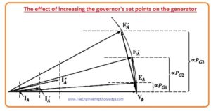
- After connecting the generator with the power system, if we set the governor of a generator at different points it is shown in a given figure.
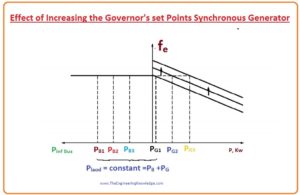
- When we change the setpoints of the governor than the frequency of the generator in case of no-load will increases.
- As the frequency of the infinite bus or power system can change due to increment of the alone generator frequency the generated power will be increased.
- This increment in the governor set points and increment frequency and voltage is also shown in phasor diagram.
- You can see from the above phasor diagram that the value of the EAsin has increased but the EA =Køw is unchanged, as EA is unchanged so the field current and the speed w will also remain same.
- Due to increment in the governor’s set points the frequency increase of the generator that causes to increment in the terminal voltage and power of the generator.
- With the increment in the output power the internal generated voltage EA does no vary but the EAsin has increased.
If output of the generator is increased until it surpasses the power spent by the load, what will happen on the system?
- If it happens the additional power produced will go back into the infinity bus.
- As the property of infinite bus is that it can receive and deliver any amount of the power without variation in the frequency so additional power produced by the generator will be spent (consumed).
- When adjustment of the active power of the generator to specified value the resultant phasor diagram of the generator will be like the above-given phasor diagram.
- Note that now the P.F of the generator is leading, that means it using reactive power Q.
How can the generator be adjusted so it supplies reactive power Q to the system?
- It can be accomplished by varying the value of the field current of the generator.
- To get this condition there are some parameters that generator should fulfill.
- The parameter is that the input power Pin =tindwm should remain constant when the field current varied.
- The prime mover of the generator should have the same value of the torque-speed characteristic curve for any set point of the governor.
- The changing in the torque-speed curve will occur only when the setting points of the governor varied.
- As we already know that the generator is connected with the infinity bus or large power system, so speed will remain constant.
- As the speed of the generator cannot be varied and set points of the generator also not varied, the output power of the generator will also constant.
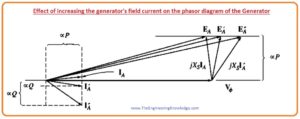
- As the output power of the generator is not varied when we changed the field current, so the distances proportionate to the power in the phasor diagram (IAcosø and EAsin ) will remain unchanged.
- When the field current increased then the flux also increased, the increment in flux cause to increase in the internal generated voltage that are directly proportionate to the flux. EA =Køw
- As the internal generated voltage increased with the flux but the EAsin will remain constant, then the phasor of internal generated voltage EA should move across the line of the constant power. It is shown in a given figure.
- As the Vø is unchanged, the angle variation of jXsIA is mentioned in figure, so the angle and the magnitude of the armature current IA will also varied.
- Note that the distance proportionate to the reactive power Q (IA sinø) has increased as a consequence.
- In simple way, the increment in the synchronous generator that is connected parallel with the large power system (infinite bus) will increase the reactive power of the generator.
Summary of Operation of Generators in Parallel with Large Power Systems
- The frequency and the output voltage VT can be regulated (controlled) by the large power system with that it is connected.
- The governor of the generator regulates the active power of the generator that is provided by the generator to the large system.
- The field current IF of the generator controls the reactive power Q that is provided by the generator to the large power system.
- It is the condition by that the generators function when coupled to a very large power system like an infinite bus.
You can also read some related topics to synchronous generator that are listed here.
Introduction to Synchronous Generator
Synchronous Generator Equivalent Circuit
Synchronous Generator Phasor Diagram
Synchronous Generator Power and Torque
Synchronous Generator Parameters
Synchronous Generator Operating Alone
Synchronous Generator Parallel Operation
Synchronous Generator Parallel with same Size Generator
Synchronous Generator Capability Curves
Synchronous Generator Transients
That all about Synchronous Generators in Parallel with Large Power Systems, if you have any questions about it, ask in comments. See you in the next tutorial Synchronous Generators Parallel with Same Size Generators.




Good
fine