
Hello friends, I hope all of you are fine. In today’s tutorial, we are going to have a look at frequency-power and voltage-reactive power characteristics of a synchronous generator. The synchronous generator was first introduced to the world for the first time in 1870 by P.N. Jablochkov. These generators are used in submissions where continuous speed is desired. The operation of this device is very modest, as we know it is not a self-starting machine. An exterior DC source is coupled with its rotor. When the rotor is revolved by the prime mover, then a rotating magnetic field is produced in its stator. Instead of an external source, a permanent magnet rotor can also be used for it, but mostly it is connected with a small generator or exciters.
In today’s post, we will have a look at its output frequency and power relationship and also discuss the relation between reactive power and generated voltage. So let’s get started with frequency-power and voltage-reactive power characteristics of a synchronous generator.
Frequency-Power and Voltage-Reactive Power Characteristics of a Synchronous Generator
Any type of generator, whether it is an alternating current or direct current generator, gets mechanical energy from some external sources that are known as a prime mover.
There are many categories of prime movers, like steam turbines, hydro, wind, or gas turbines.
It does not matter either which type of prime mover is working on the generator; its speed with which it rotates the generator decreases when the load on the generator increases.
To maintain the speed of the prime mover, a speed limiter is introduced on the generator that is called the governor mechanism; it controls the speed of the prime mover to reduce it in case of any variation in the load or high-power demand.
The governor adjusts the prime mover speed in such a way that it shows a dropping characteristic (it is a curve of a generator that specifies a decrease in voltage when load increases on the generator and uses a high amount of power) with the increment in a load of the generator.
The speed drop equation of the prime mover is written as
.
SD = (nnl – nfl) nfl x 100
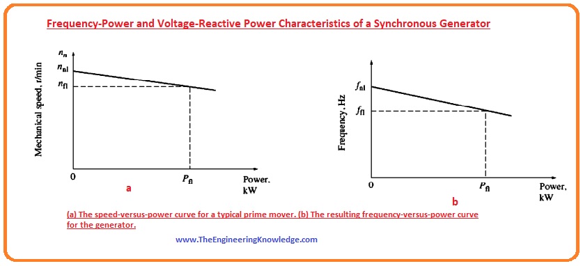
- In this equation, the nfl is the speed of the prime mover when the generator is working at full load and nnl is the speed when there is no load connected with the shaft of the generator.
- Some prime mover has speed drop of almost two to four %.
- Most governors have some points of variation that permit the speed of the prime mover to change when the no load is connected to the generator.
- In a given diagram, the graph between power and speed is shown.
Frequency and Power of Synchronous Generator
- The expression that explains the relation between the speed of the generator’s rotor and its stator’s frequency is given as.
fe = nmP/120
- In this equation the.
- fe is the speed of the frequency of the generator’s stator.
- nm is the rotation speed of the rotor.
- P is no of poles of the generator.
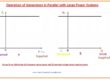
- The graphical representation of the frequency and power is drawn in given figure.
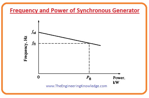
- This kind of graphical representation of the frequency and power is very useful for the parallel operation of the generator.
- The quantitative relation of frequency and power can be written as.
P = SP(fnl – fsys)
- P is the output power of the synchronous generator.
- fnl is the frequency of the generator when there is no load at a shaft of the generator.
- fsys is the frequency of the system it can be 50 or 60.
- SP is the slop of the characteristic curve that is formed between the frequency and the power of the generator, and it is measured in Kw/hz or Mw/hz.
Voltage and Reactive power of the Synchronous Generator
- The equation that we discussed can also make this type of relation between the reactive power and the terminal voltage of the generator.
- As we discussed in the synchronous generator operating alone article, when the load on the generator is inductive, there is a voltage loss at its output.
- When the load is capacitive the value of the output voltage VT
- The graphical representation among the terminal voltage and the reactive power is shown in a given figure, and it also shows the drooping characteristic of the synchronous generator.

- We can see from the figure that the graph is a straight line; it is not naturally a straight line, it is due to voltage regulators. That makes it linear by maintaining the value of the voltage.
- The location of the curve can be shifted up and down in the graph by changing the no-load voltage point location; it can be done by the voltage regulators.
- Like the power frequency, these characteristics (VT and Q) also play a very important rule in parallel operation of the synchronous generator.
- The relation between VT and Q can be written like the relation that we make between power and frequency in the equation given below if the output of the voltage regulator shows linear behavior with the variation in reactive power (Q).
P = SP(fnl – fsys)
- The important point is that when a generator is working alone, the active power (P) and the (Q) generated by the generator depend on the load connected with the generator; both powers are not regulated by the governors of the generator.
- So, the frequency fe frequency and reactive power Q of the generator are controlled by the governor of the generator and the terminal voltage is controlled by the field current of the generator.
Conclusion
- From the above discussion, we can conclude some points that are described here.
- The active power P and reactive power Q generated by the generator depend on the quantity of the load connected with the generator.
- The governor of the generator controls the frequency of the system fe.
- The field current of the generator controls the output voltage VT of the generator.
You can also read some related topics to the synchronous generator that are listed here.
Introduction to Synchronous Generator
Synchronous Generator Equivalent Circuit
Synchronous Generator Phasor Diagram
Synchronous Generator Power and Torque
Synchronous Generator Parameters
Synchronous Generator Operating Alone
Synchronous Generator Parallel Operation
Synchronous Generator parallel with Large Power system
Synchronous Generator Parallel with same Size Generator
Synchronous Generator Capability Curves
Synchronous Generator Transients
That all about Frequency-Power and Voltage-Reactive Power Characteristics of a Synchronous Generator I have mentioned each and everything related to this topic. If you want to know something more can ask in comments. See you in the next tutorial.

well written
Thanks for your article. I would love to say a health insurance brokerage also works for the benefit of the coordinators of any group insurance policy. The health agent is given an index of benefits wanted by anyone or a group coordinator. What any broker can is hunt for individuals or even coordinators that best match up those demands. Then he shows his recommendations and if each party agree, the actual broker formulates binding agreement between the two parties.