

 Hello friends, I hope all of you are fine. In today’s tutorial, we are gonna have a look at Open Circuit Test and Short Circuit Test of Synchronous generator and their relationship. There are many factors of electrical power networks that rely on the usage of the generator models for the estimation of the power system behavior, the correctness of these estimations relies on the correctness of the parameters of the generator used in the system. Some of these parameters are not easy to find so producers of the generators mentioned these parameters on the datasheet.
In today’s post, we will have a look at the different parameters of a synchronous generator that should be examined before the installation of the generator. To easy understand of the parameters of a generator, you must have knowledge of the synchronous generator resultant circuit. So, let’s get started with the Open Circuit Test and Short Circuit Test of Synchronous Generator.
Open Circuit Test and Short Circuit Test of Synchronous generator
- During the measurement of the resultant circuit of the synchronous generator, we find the three parameters, that are very important to study the complete performance of the real-world synchronous generator.
- These three parameters are described here.
-
- The armature resistance.
- The relation between field current and internally generated voltage EA
- Synchronous reactance Xs
- To find these three parameters we will perform some tests on the synchronous generator that are described here with the detailed
Open Circuit Test of the Synchronous Generator
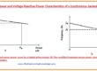
open circuit characteristics of synchronous generator is explained here
- To accomplish this test the generator should move at its rated speed, no-load should be at its terminals, and the value of the field winding current should be 0.
- After following these steps, we will vary the field current step by step and calculate the terminal voltage at each step.
- As there is no load at the output terminals of the generator, so there will be zero armature current.
- Hence the internal generated voltage EA will equal to the phase voltage Vø.
- By using this data, we can construct the curve among the internally generated voltage that equals the terminal voltage and the field current.
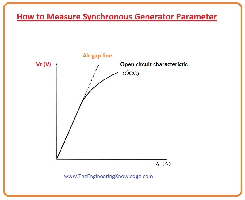
- This graph between EA and the field current is known as the open-circuit characteristic (OCC) of the synchronous generator.
- By this graphical representation, we can find the value of internal generated voltage EA any value of the field current.
- The graph of the open-circuit characteristic is shown in a given diagram,
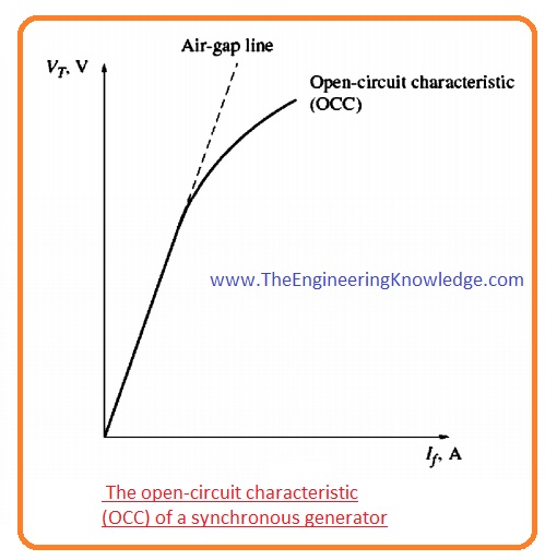
- You can observe from the graph that at the start the curve is a straight line then it is not a straight line it due to saturation.
- The reluctance offered by the un-saturated region is lesser than the reluctance of the air gap, at the start when the iron is not saturated the field current and the terminal voltage are in direct relation with each other.
- When iron gets saturated, the reluctance offered by the iron becomes larger than the increment in the flux is not directly proportional to the field current, so the curve is not a straight line after some interval.
- The linear part of the open-circuit characteristics is known as the air gap line.
Buy Here Short Circuit Test of Synchronous generator
Short Circuit Test of Synchronous generator
Short circuit test of Synchronous Generator
- To do a short circuit test first of set the value of field current at 0 and connect the output terminals of the generator by the ammeter.
- After that find the value of the armature current (IA) by changing the field current.
- This graph among the field current and the armature current known as the short-circuit characteristic (SCC).
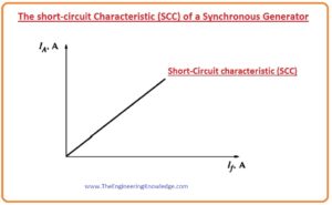
- You can see that it is a linear graph.
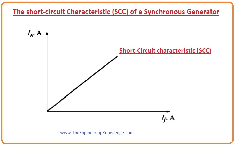
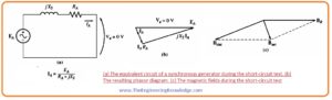
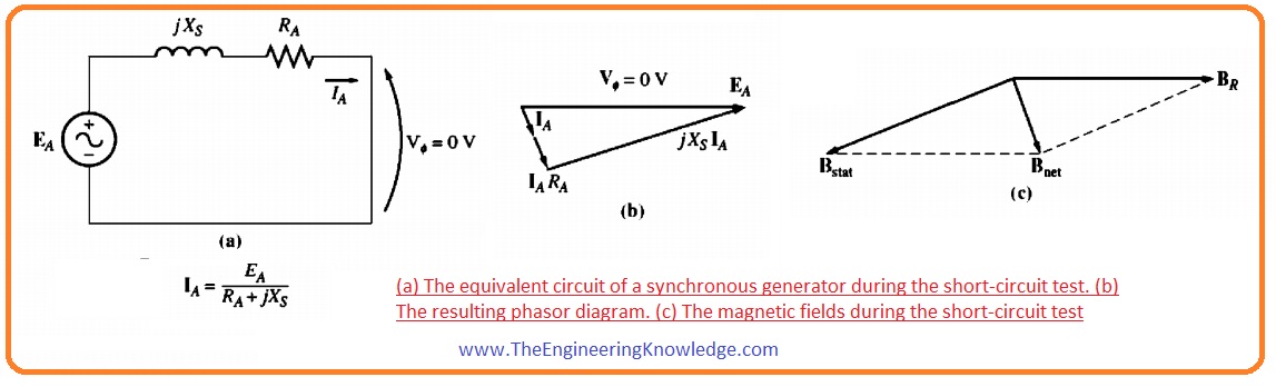
- To understand this straight-line behavior let’s have a look at the equivalent circuit of the synchronous generator when it is short-circuited this circuit is shown below.
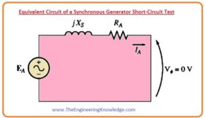
- From this circuit, you can find the value of the armature current (IA) that is given here.
IA =EA/(RA+jXs)
- The magnitude of the armature current is given here,
IA =EA/√(R2A+X2s)
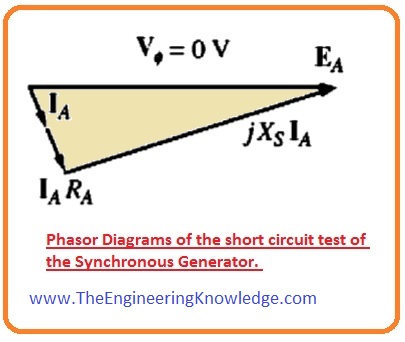
- The phasor diagrams of the short circuit test of the synchronous generator are shown below.
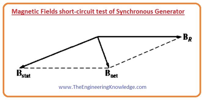
- The fields during the short circuit test are physically shown in a given diagram.
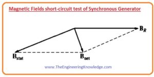
- As the stator field Bs crosses the effect of the rotor magnetic field (BR) so the total field Bnet has low value.
- As the value of the Bnet is lesser so the generator is un-saturated short circuit characteristic curve is linear.
- To recognize what data these two features have output, note from a given figure that the Vø is 0.
- From this figure, the interior impedance of the generator is given here.
Zs = √(R2A+X2s)
= EA/IA
- As we know that synchronous reactance Xs is greater than the armature resistance RA so this equation becomes.
Xs= EA/IA
= Vø,oc/IA
- If the value of the internally generated voltage (EA) and armature current (IA) is known, we can compute the value of the synchronous reactance.
- Measure the internal generated voltage EA from the generator short circuit test characteristic (OCC) at the specified value of the field current.
- Measure the short-circuited current IA at the field current from the open-circuit characteristic (OCC)
- Put the values of the internal generated voltage EA and the IA in the given below equation and find the value of the synchronous reactance.
Xs= EA/IA
- There is some issues for this technique to the measurement of the synchronous reactance.
- As the internal generated voltage EA is measured from the OCC at that point where the generator is partly saturated for a higher value of the field current and the armature current (IA) is taken from the SCC where the generator is un-saturated for all values of the field current.
- So, at the larger field current, the internal generated voltage calculated from the OCC at a specified value of the IF is not similar to the internal generated voltage measured from the SCC at the same value of the field current IF.
- This difference affects the value of the synchronous reactance X
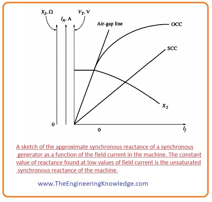
- So, the result by this method can be applied to the saturation point, the unsaturated XS can be measured by this equation at any value of the IF in the straight-line part of the open-circuit characteristic (OCC).
Xs= EA/IA
- The estimated value of XS fluctuates with the gradation of saturation of the open-circuit characteristic curve, therefore the value of the XS to be used in a specified problem must be measured at the estimated load on the generator.
- A graph of estimated (approximated) Xs as a function of IF is in a given figure.
- It is significant to identify the resistance of winding as well as its Xs, resistance can be measured by by providing dc voltage to the windings when the generator is not working
- During the dc application, the value of the reactance of the winding will be 0.
- This method does not give proper results because the alternating current resistance is somewhat higher than the value of the direct current resistance.
Short-Circuit Ratio Synchronous Generator
- It is the ratio of the field current needed for the rated voltage at open-circuited conditions to the field current needed to produce the rated armature current at short-circuited conditions.
- Though the short-circuit ratio tells nothing new that is not we know about synchronous generator reactance. But in industries, this fact is used so we should have knowledge of it.
Short circuit test of alternator
The short circuit test for the alternator is done to find the value of synchronous impedance that provides the total inner resistance. These parameters are used to design and work of power systems and help to solve different problems existing in the alternator
To do these test alternator move the rated speed and the field current is controlled t value that generates the rated voltage at the terminal alternator. The terminal voltae are connected with use ammeter at alternator terminals. As a result, the current flowing through the meter is circuit current.
This formula is used to measure teh value of synchronous impedance
Zs = Vrated / Isc
here
- Zs is the value of synchronous impedance measured in ohms
- Vrated is the value of rated voltage in volts
- Isc = short circuit current
short circuit test for alternator
- Remove the load with the alternator
- add ammeter to terminals of alternator
- MOve teh alternator at rated speed with the use of a prime mover.
- the rated voltage generated with the use of field current
- Make short between alternator terminals through connection ammeter between terminal
- Measure short circuit current.
- measure the synchronous impedance
Open circuit test of an alternator
This test is performed to measure the open circuit voltage and no load current of the alternator for different values of field current. The Open circuit voltage or OCV is the voltage produced by the device if it has an open circuit terminal wot the is no load connected. The field current is provided to excite the alternator to generate the required value of open circuit voltage
How to do an open circuit test on an alternator:
- Remove the alternator from the system
- At output terminals connected to a voltmeter
- With field winding of alternator connected ammeter in series combination
- rated speed set for the alternator
- Change the field current and measure the different values of OCV at each change in the field current.
You can also read some related topics to a synchronous generator that is listed here.
Introduction to Synchronous Generator
Synchronous Generator Equivalent Circuit
Synchronous Generator Phasor Diagram
Synchronous Generator Power and Torque
Synchronous Generator Operating Alone
Synchronous Generator Parallel Operation
Synchronous Generator parallel with Large Power system
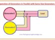
Synchronous Generator Parallel with same Size Generator
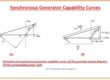
Synchronous Generator Capability Curves
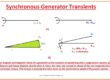
Synchronous Generator Transients
That is the detailed article on the Synchronous Generator Parameter we did different tests for finding different parameters if you have any query ask in comments. See you in the next tutorial Synchronous Generator Operating Alone.

We’re a gaggle of volunteers and starting a new scheme in our community.
Your site provided us with useful info to work on. You’ve performed a
formidable process and our entire neighborhood will probably be thankful to you.