 Hello friends, I hope all of you are fine. In today’s tutorial, we are gonna have a look at the Parallel Operation of Synchronous Generator. Nowadays it is rare in an electrical system that any synchronous generator providing power to its loads is lonely. In certain conditions, like if somewhere supply is disconnected from the grid, then there is a single generator can be used to provide power to the load, but its normal generator does not work alone. In normal working conditions always more than one generator is working together in parallel. An example of this system is the United States of America grid station, where almost a thousand plus generators provide power to the load in the system.
In today’s post, we will have a look at how a generator works in parallel operation of generator conditions, its features, connections, and some other conditions. So, let’s get started with a Parallel Operation of a Synchronous Generator.
Parallel Operation of Synchronous Generator
- Before studying the parallel operation of the generators, first we discuss the advantages of parallel operation. These are described here.
Advantage of Parallel Operation of Synchronous Generator
- More than one generator can supply power to a larger load.
- Many generators in a system enhance the consistency of the system, in certain cases, if one generator is not working then there will be no effect on the total load, which can occur in the case of a single generator.
- If more than one generator is working in the system and we have to repair someone from the system, we can easily remove it and repair it. Others will continue to deliver power to the load.
- If we have one generator of higher power rating in the system and it not providing power to the load at rated condition, that’s not good for the system. Instead, if we use many generators of fewer power ratings and few of them are working and providing power to the load at rated conditions. So, it will be good for the system to use more than one generator with a lower rating than one generator with a higher rating.
Conditions for Parallel Operation of Synchronous Generator
Conditions for the parallel operation of the generator are explained here
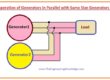
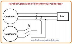
- In the above diagram, you can see that there are two generators connected in parallel. The first generator is G1 provides electrical power to output with the second generator G2, which is connected with the first by a switch S
- If we close the switch randomly at any time and connect these generators it can cause of serious disaster for both the generator and load.
- If the voltage at the terminals of both generators is not the same, it will produce such a high current that will damage the generators.
- To eliminate this situation there should be all three phases of both generators should be at the same voltage level and have the same phase angles.
- It means phase a has an equal voltage level to phase a’, phase b is equal to phase b’ and c is equal to c’.
- To get this same matching of the phases we must follow some conditions that are described here.
- The root mean square (rms) voltage of these 2 generators should be the same.
- The phase sequence of both of the generators should be the same, which means a is connected with a’ of the other generator, b with b’, and c with c’.
- The phase angle of two similar phases should be equal. This means (a) the phase of both the generators have the same angle, and so on.
- The frequency of the generator that is going to connect also called the ongoing generator should be a little bit higher than the generator that is already in working condition.
- Now we explain these 4 conditions in detail.
Condition 1 and 3:
- To have similar voltage at the terminals of both generators there should be the same value of root mean square voltage and their phase angle that are described in condition 3. The voltage at phases a and a’ will remain the same during working if these to follow conditions one and three.
Condition 2:
The phases that are to be connected have a similar phase sequence.
- If the phase sequence is not the same, (as shown in the given diagram) or one phase like (a) phase is connected with the same phase but other 2 phases are not connected properly with the similar phases.
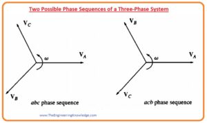
- If these 2 generators have this type of sequence then there will be nothing happen at phase a, as it is connected correctly but at the other 2 phases b, c such a short circuit will occur that will damage both generators.
- To solve this issue only change the position of the 2 phases at any one generator out of the three phases.

Condition 4:
- If the frequency of the ongoing generator is not slightly higher than that of running the generator, there will a huge amount of transient current will be produced until the frequencies of both generators become equal.
- The frequencies of these 2 generators should be almost equal, but not exactly the same value, which means the ongoing generator frequency should be a little bit higher than another generator.
- There should be some difference among the frequencies of 2 generators so that the incoming generator phase angle will change according to the phase angle of the running generator.
- By this method, the angles among the voltage can be observed and the S1 can be closed when both generators have same value of the voltages.
Procedure for Paralleling Generators
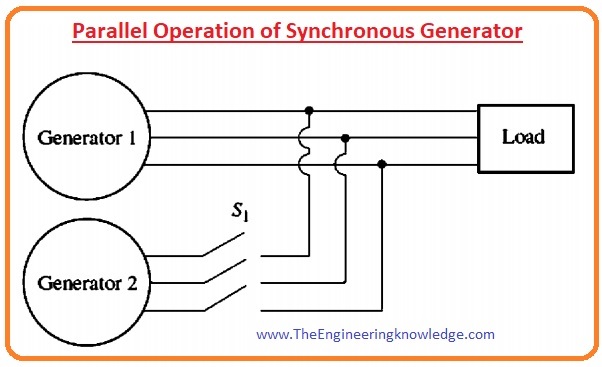
- In the given diagram there are generators G1 and G2, you can see that G1 is already connected with the load and G2 has to connect with the system.
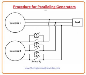
- To connect the generator G2 we must apply these steps.
- First, we have to adjust the voltage of the generator G2 equal to the system. For this monitor, the voltage of this generator by the volt-meter and set equal to the system.
- 2nd is to check the phase sequence of the G2 and match it with the system frequency there are many methods to check the phase sequence some are described here.
- The first method is to connect small rating induction motors with both generators one by one and observe their rotation direction.
- If the direction of the rotation is the same for both generators then the sequence is the same.
- If the rotation direction of the motors is not the same there is no same phase sequence, for same sequence, just change the two phases’ connection of the incoming generator.

Three-Light-Bulb Method for Checking Phase Sequence
- There is another method to check the phase sequence of the generator.
- In this method, there are 3 bulbs connected with the open terminals of the incoming generator with the switches that connect it to the system. it is shown in a given diagram.

- If there is a difference among the sequence of the phases, then the bulb glows (it means high phase difference) and then becomes darker (less phase difference).
- If these 3 bulbs glow and dim at the same time, then both of the generators is connected with the same phases.
- If the bulbs do not glow at a time or glow one by one then there will be different phases that are connected, to solve this problem one of the sequences should be changed.
- The other point for parallel operation is that the frequency of the incoming generator should a little bit higher than the working generator.
- The value of the frequency is set by the frequency meter and then measured from the phase changing (difference).
- The frequency of the coming generator should be slightly higher than the system so that when it is connected with the system it works as a generator, not as a motor.
- When the frequencies of both the working and incoming generators are almost the same, the 2 generators will vary phase according to each other gradually,
- The variations in the phase are detected, and when the angles of the phases are the same, the switch that joins both generators will close.
How can we tell when the 2 generators are in phase?
- The simplest method is to watch the three bulbs that are connected with the circuitry as shown in the above figure.
- When all three bulbs glow at a time there is no phase difference and phases are connected in the same sequence.
- This method works but has some limitations, sometimes not working accurately.
- Another technique that can be used for checking the phase sequence, is the use of
- It is an instrument that calculates the phase angle difference among (a) phases of the generators.
- In the given diagram, you can see the synchroscope.
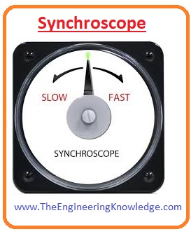
- You can see the needle on the meter that will indicate the phases if it is at zero and a one-eighty degree then the voltages are in phases.
- As we studied earlier the frequencies of both generators are different, so the angle of the phases will vary on the meter gradually.
- If the frequency of the incoming generator is higher than the working generator (that is in our case), the angle of the phase will advance and the pointer (needle) on the meter will move in the clockwise direction.
- If the frequency of the incoming generator is less than the running generator, the needle of the meter will move in the anticlockwise direction.
- When the needle of the meter is either 0 degrees or 1800 it means that the phase sequence is the same, so we can close the switch to make contact among the generators.
- You can note that this meter tells about the only single phase, that we discussed. It does not tell about the sequences of the phases.
- For high-rating generators that are connected to a power system, parallel operation of the incoming generator is done by the computer, a synchroscope is not used for such systems.

Precautions During Parallel Connection
- All connected generators must have same voltage value
- There must be the same phase angle for all connected generators
- All generators have a balanced load
- Before the parallel combination, all generators must be synchronized
- All generators must have the same operating frequency
- Polarity must be the same
Generator parallel operation condition
generator parallel operation conditions are the terminal voltage of the incoming generator and altern that is to connect parallel or with BUSBAR voltage must be equal. The frequency of the produced voltage of the incoming generator and the frequency of the voltage of the busbar must be the same.
Faqs
What is parallel operation of a synchronous machine?
- The electric power station comes with many synchronous generators working in parallel combination with each other.
- The benefit of parallel operation is that if any machine is not working then other working machines can provide power to load.
Why is parallel operation of synchronous generators important?
- Many generators provide power to larger loads thatn single machines. So larger number of generators increases the reliability of the power system, as if anyone not working not affect the complete system
What is parallel operation of generators?
- In this configuration, parallel generators of the same type, and size get double wattage. This connection work with each other in a way that increases the wattage that goes to connected with the system.
What is the method of parallel operation?
- Parallel operation of dc generators is process of connection of two or more generators in parallel configuration to increase total power output, enhances reliability and helps flexible working power supply system
You can also read some related topics to synchronous generators that are listed here.
Introduction to Synchronous Generator
Synchronous Generator Equivalent Circuit
Synchronous Generator Phasor Diagram
Synchronous Generator Power and Torque
Synchronous Generator Parameters
Synchronous Generator Operating Alone
Synchronous Generator parallel with Large Power system
Synchronous Generator Parallel with same Size Generator
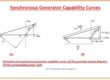
Synchronous Generator Capability Curves
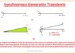
Synchronous Generator Transients
That is a complete article on the Parallel Operation of Synchronous Generators if you want to know something more can ask in the comments. See you in the next tutorial Synchronous Generators in Parallel with Large Power Systems.