Hello readers, welcome to the new post. Here, we will learn PCB Heat Dissipation Techniques. Electronic devices are now very commonly used. These devices are made with the use of PCB boards, such as phones, laptops, and different electronic devices. However, ,electronic components have small sizes and do not easily manage heat due to their complicated structure. In this post, we will discuss different PCB heat dissipation methods mostly used in electronic devices and projects. So let’s get started with PCB Heat Dissipation Techniques.
Why Heat is a Problem in PCBS
When current flows in electronic components, the load increases. The heat generated by electronic components is produced based on circuit design, power used, and features. If components are not accurately connected, improper ventilation and faulty assembly result in the board going overheating.
PCB can handle to some extent, but high temperatures can cause problems for boards. Some bad effects factors can result in board working. of heat on boards are component oxidation, disruption of circuit lines, loss of structure quality, etc. These factors can affect in-board working. If the board has a high temperature for a longer duration, it can stop working and also the device’s circuit.
Why PCB Heat Dissipation Techniques Are Important
The electronic device that needs more power to operate produces more heat. Different components, such as voltage regulators, controllers, and power transistors, get heated due to high loads.
Older mobile phone models get heated due to higher short conversion. If there is no cooling fan on the laptop, the result is heating of the system. If we put the circuits of laptops in an enclosed casing, the result is two-time the heat.
Different components have a limited temperature range for their work, and if the temperature is higher than the limit, the component will be affected. Such a microcontroller will use more power at high temperatures than at room temperature.
If electronic components face heat for a longer time, they work for a short duration. Normally, the increase of 10 centigrade reduces working life to half.
Causes of Heat in PCBs
High Power Components
Different components, such as amplifiers, CPUs, power regulators, and drivers, are important for heat dissipation based on current passing through them and voltage losses. Heat is produced in silicon dies and contact junctions.
Traces and Layers
Traces that have high currents cause heating due to the resistivity of conductors. Internal layers with larger high-current plans are affected by heat.
Vias
Vias between layers and causes heat through conduction via barrel resistance in high-current paths.
Inductors
Inductors winding resistance and core losses transform electrical energy into heat. Iron powder and ferrite material come with high core losses.
How to dissipate heat in PCB
Thermal via arrays
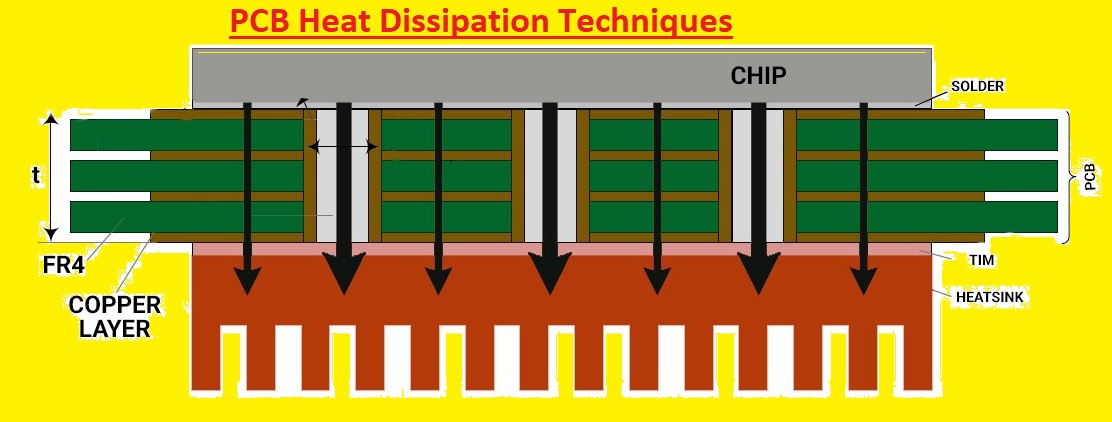
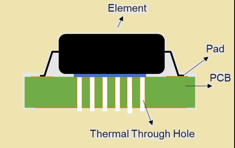
PCB can be connected to the onboard heat sink by making thermal via an array over the copper-filled area. The idea to do this is to heat flow from component to copper part and dissipate through air from vias. Normally thermal via array is used for power management modules and components with a combination of thermal pads.
While applying thermal via array, note that it needed to have a larger diameter of about 0.1mm for direct heat dissipation. A larger number of vias increases heat dissipation.
Wider Traces
Copper traces that have high current cause heat generation. So it is good to increase the width of traces to increase heat dissipation. It also reduces the thermal resistance of trace and heating spots.
Heatsinks and Cooling Fans
Passive heat dissipation methods such as thermal via arrays may not be well for heat dissipation. So connect the heatsink and fans on board. Heatsink is connected to components that produce high heat, normally CPU, MCU, voltage regulators, and power transistors.
A closed-design cooling fan is connected to dissipate heat to air.
What are PCB Heat Dissipation holes?
What are PCB heat dissipation holes?
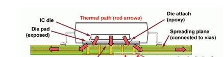
PCB heat dissipation holes, also known as PCB thermal vias, are processes used to dissipate heat to the rear side of the board through holes in the board.
They are configured close to heat-generating components. Heat dissipation holes are processed to increase the heat dissipation effect of surface-mounted components through the use of a board-like heat sink. Their structure is through holes in boards.
In single-layer and double-side boards, this method is used for reducing thermal resistance by connecting copper foil on both sides of the board, increasing area and volume for heat dissipation.
In the case of a multi-layer board, the same benefits can be achieved through connection planes between layers or certain layers.
How heat transfers?
Conduction
Conduction transfers heat between solids through direct molecular contact. Copper, with its high thermal conductivity, conducts heat through PCB traces and layers.
Convection
In this process, airflow is used overboard to remove heat through exchange fluid. Fin can help to increase convective heat transfer.
Radiation
From high-temperature bodies, electromagnetic waves are released. The heat dissipation rate is directly proportional to the temperature difference between the board and its surroundings.
Tips for heat dissipation of PCB
Arrangement of Components
Components on board must be configured and properly aligned with heat-emitting features. The components that have low heat-emitting features and weak heat-resistance features, like small-signal transistors and small ICS, are connected at the entrance of the cooling airflow.
While high heat-emitting components and good heat resistance, such as power transistors, are connected at low flow of cooling airflow.
For the horizontal direction, high-power components are configured close to the edge of the board for a short heat transfer path.
For vertical direction, they must be close to the top of the board to reduce the effect on the temperature of other devices.
Faqs
What are the methods of heat dissipation?
- Conduction
- Convection
- Radiation
- Evaporation
- Phase change
What is the heat dissipation process?
- The process of heat dissipation involves low heat from hot bodies to cold bodies.
What is the application of heat transfer knowledge in the engineering field?
- Heat transfer knowledge is used in different engineering fields, like
- Electrical engineering
- Mechanical engineering
- Chemical engineering
- Civil engineering
- Aerospace engineering
- Automotive engineering
- Industrial Engineering
- Heat transfer knowledge is used in different engineering fields, like
What is the purpose of heat dissipation?
- Heat dissipation is used to transfer thermal energy to other places and minimize temperature so that the whole body can have balance with temperature and the surrounding environment.
What is the process of dissipation?
- Heat dissipation is the motion of heat away from the source in the surrounding environment, and it occurs through conduction, radiation, and convection.
What materials are used for heat dissipation?
- Heat dissipation components have different shapes like plate shapes, needle-like or bellows-like shapes, and pipe shapes, and commonly used materials are metals, ceramics, and graphite.
What is the unit of heat dissipation?
- Heat dissipation is measured in BTU/h, and 1 W equals 3.4121 BTU/h.
What is the formula for heat dissipation?
- The formula for heat dissipation is:
- Q = ∆T x R
- Q is the heat dissipation rate, where Q is the heat dissipation rate ∆T, the difference between the temperature of hot and colored bodies, and R is thermal resistance.
- The formula for heat dissipation is:
What is the heat dissipation rate?
- The rate of heat dissipation is given through Fourier’s Law of conduction. Q/A = – K dt/dx. Q = heat dissipated. A = area perpendicular to heat flow. K = thermal conductivity of that material
What is the heat dissipation time?
- When the system is heated, time is taken to reach a steady state condition.
What is the heat dissipation limitation?
- The heat dissipation limitation is the highest heat value that can dissipate.
What are some common overheating problems caused by poor PCB thermal design?
- High heat can cause improper wiring and reduce working life or permanent damage to different components such as ICs, capacitors, and magnetic. Heating points also produce thermomechanical stresses and substrate delamination.
How can you protect PCB from heat?
- PCB pads must come with enough thickness for good heat management over the large area. You can use a sink at a lower layer of heat transfer. With that, solder paste must be used in an accurate amount so components do not float on molten solder during reflow.