All Types of Electrical Transformer symbols and diagrams. In the field of electrical engineering, transformers main components. Through the use of the phenomenon of electromagnetic induction, they are used for the transfer of electrical energy from one circuitry to another. There is different types of transfer used in electrical power systems based on construction and uses. Each has its own symbols and schematic diagram. Here we will cover the different transformer diagrams and symbols in this post. So let’s get started with Transformers Electrical Symbols
Introduction to Transformer
- A transformer is an electric device that changes the voltage level from high to low or low to higher. Based on the application, it changes voltage levels. Electrical engineers who are handling the transfer must know transformer symbols.
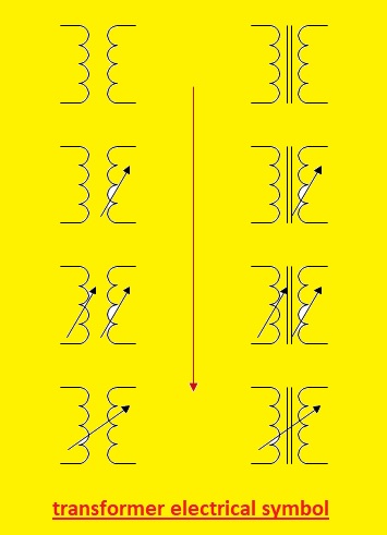
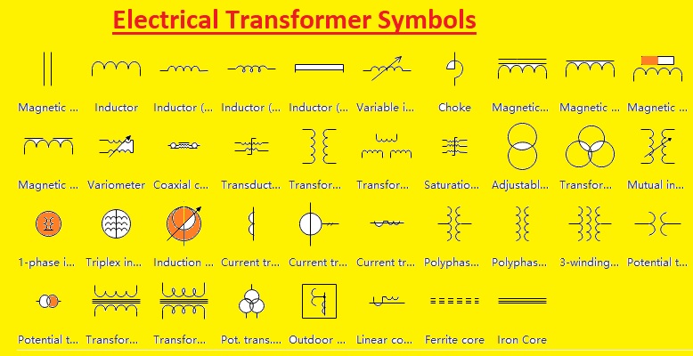
Electrical Transformer Symbols
- Transformers’ Electrical Symbols provide the function of devices and their work to make easy knowledge of their features and related parameters. Here you can see the common electrical symbols for transformers used in electrical diagrams:
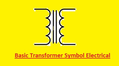
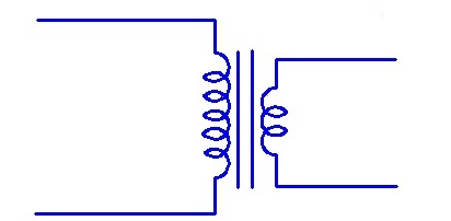
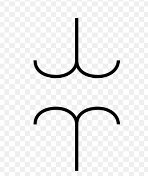
Basic Transformer Symbol Electrical
- In the basic transformer symbol, electrical, primary and secondary coils are separated using dotted lines. The voltage supply is connected at primary windings and the load is at secondary windings
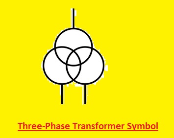
Three-Phase Transformer Symbol
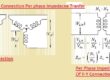
- A 3-phase transformer comes with 6 windings wounded about a single core. There are three winding on every side, the primary and secondary sides. But winding can be connected in star or delta configuration.
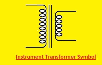
Instrument Transformer Symbol
Instrument transformer can be a current transformer or voltage transformer. A current transformer is an instrument transformer used for reducing high curent in line to the safe value of current. This current generated in the secondary is proportional to the current at the primary and it is measured with Ammeter.
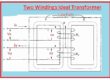
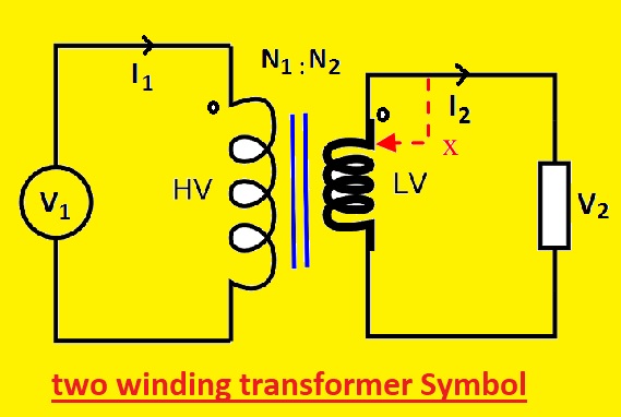
Two Winding Transformer
This is a symbol of a winding transformer. Two windings transformers are made with two winding connected through magnetic flux.
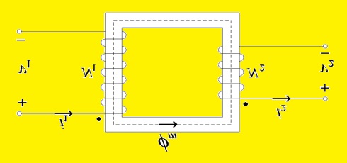
Single Phase two Winding Transformer
In this transformer, there are two primary and secondary winding used with a single phase. It has two primary and two secondary terminals.
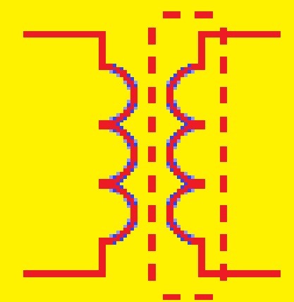
Single Phase Separate Winding Transformer
This transformer comes with a separate winding for primary and secondary terminals. The double dashed line denotes two terminals for every winding.s

Shielded Transformer
The shielded transfer comes with an electrostatic shield between primary and secondary winding that saves the transfer of high spikes of voltage and frequency noise. The shield is grounded and capacitance between the shield and primary winding saves noise transfer in the result of high-frequency
Moving magnet Transformer
The voltage in this transformer winding is induced through the movement of a magnet near the winding. The phone cartridge uses an MM transformer and it transforms the movement of the stylus into an electrical signal through a moving agent connected with tips.

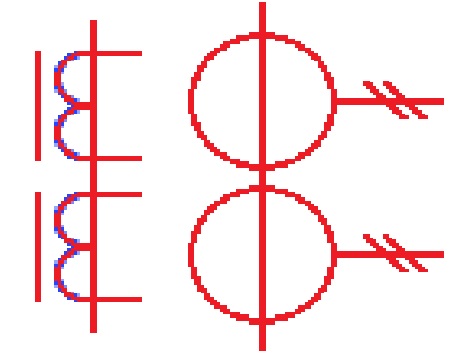
Dual Core Current Transformer with Two Secondary Lines
It comes with two crosses each for the single secondary winding. Every winding provides a different turn ratio for access to two different current ratios on each single winding.
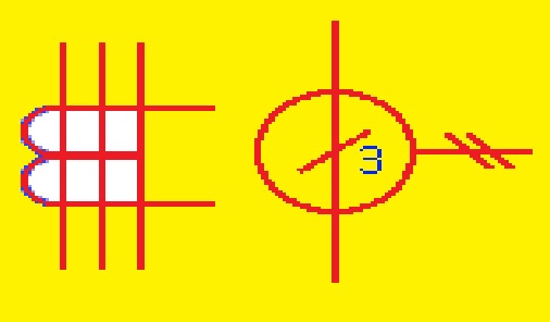
Current Transformer with 3 Conductors
This transformer is also called CBCT or core balance curent transformer. it has three conductors running through cors. The total vector cusm of current in the normal state is 0. If there is an earth fault current difference comes through CBCt which is connected with the alarm system.
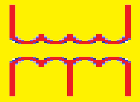
Center Tapped Transformer
The center-tapped transformer comes with a tap point in the middle of the secondary winding that helps to access a half number of turns in the secondary winding. The voltage between the center tap point and any endpoint of winding is half of that winding.
Transformer with Winding Polarity
The winding polarity in the transformer is denoted with a dot convention. if current enters the primary dotted terminal voltage induced in the secondary dotted terminal is positive. If curent left primary dotted terminal voltage induced in secondary dotted terminals is negative. They are used for connection transformation in parallel for increase the capacity.
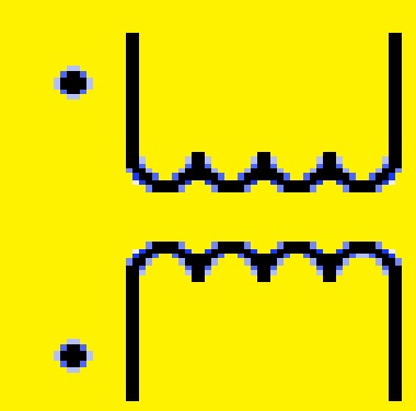
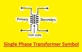
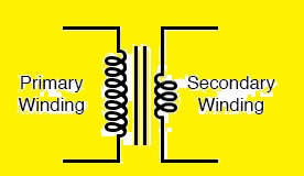
Single Phase Transformer Symbol
- single-phase transformer is a very commonly used type of transformer. It has two windings primary and secondary windings with a magnetic core to make a symbol of the transformer. The secondary windings are connected with the load and input supply with primary windings. In the symbol, there is a single line that has an arrow or dots connected to the voltage source is a symbol of primary windings. Two parallel lines that are added arrows end connected to the load are called secondary windings
- Here is the single-phase transformer’s symbol.
- Two dots in the symbols on windings are directions of current flow. The step-down transformer is used where current flows from primary windings to secondary for voltage to decrease. For a step-up transformer, current flows from secondary to primary windings, and voltage increases.
- A single-phase transformer diagram shows the symbol and details the transformer’s ratings, which are primary and secondary windings power ratings, and current.
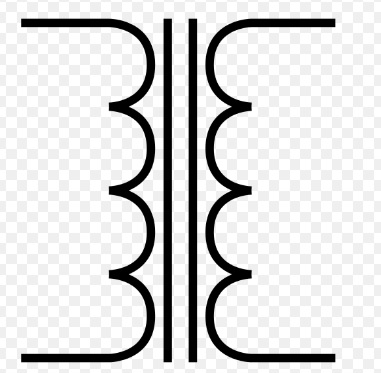
Iron Core Transformer Symbol
The core of this transformer is created with the use of iron. The iron comes with high magnetic permeability that helps to carry high magnetic flux increasing induction between windings. The drawback of the iron core is eddy curent losses that are based on power supply frequency. So used for low-frequency uses.
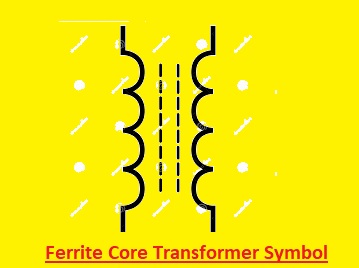
Ferrite Core Transformer Symbol
This transformer is made with the use of a ferrite core. Ferrite is a magnetic material that comes with high magnetic permeability that increases flux in the core of the transformer. With that ferrite has low electrical conductivity that reduces eddy current losses in core.
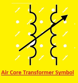
Air Core Transformer Symbol
This transformer comes with an air core and does not have magnetic coe, then winding is wounded about plastic or there is no core. There are core losses in the magnetic core that increase with frequency so an air core transformer is used where radio frequency is involved.
.
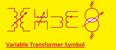
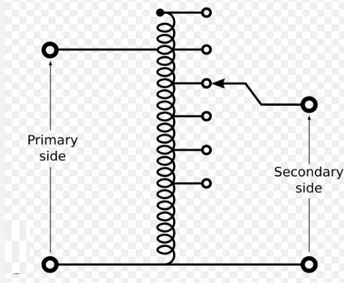
Variable Transformer Symbol
The variable transformer can provide variable secondary voltage from the same primary voltage. It can change the output voltae through varying numbers of turns or using different tap points or through variable coupling. The variac is a common variable autotransformer.
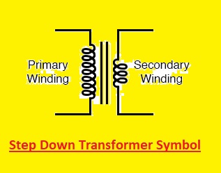
Step Down Transformer Symbol
The step-down transformer converts the high primary voltage into a low voltage at the secondary. it also transforms low primary current into high secondary current. The step-down transformer comes with low turns in the secondary winding and then the primary winding. The conversion is based on the turn ratio of the transformer.
Step-Up Transformer Symbol
The step-up transformer transformer has low primary voltage into high secondary voltage. it also converts high primary current into low primary current. it is used for a transmission line to reduce line losses in transmission line and also to meeting the voltage needed in the circuit. it comes with low number of primary turns than secondary windings.
Autotransformer Symbol
This transformer comes with winding is wounded about the core made with iron. The iron core increases magnetic flux that increases self induction in turns.
Isolation transformer Symbol
- An isolation transformer comes with a portion between input and output circuits without any connection between physical or direct. Isolations transformed offers galvanic isolation, there is no conductive path that exists between source and load. This isolation is used for protection from electric shock, controlling electrical noises in sensitive devices, or transformer power between two connected circuits.
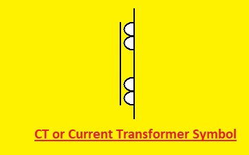
CT or Current Transformer Symbols
- A current transformer is an instrument transformer used for reducing high AC curent into low safe values for measuring processes.
- The current generated in the secondary is proportional to the curent in the primary and measured by connecting with a conventional Ammeter.
pt symbol electrical or Potential Transformer Symbols
- It is also an instrument transformer used in a power system for voltage transformation. it transforms high voltage to low voltage for measuring and protecting features
- Here is the diagram of a potential transformer:
Symbol of Voltage Transformer
- A voltage transformer is used to step down and reduce the voltage system to a level that is safe. It work allowed the energy meter to monitor the operation of electrical connections, which can have a higher voltage than normal working accurately.
- Listed below is the voltage transformer’s symbol:
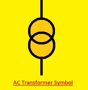
AC Transformer Symbols
- The Current transformer is used to reduce or multiply ac current. It generates current in the secondary that is proportional to current in the primary.
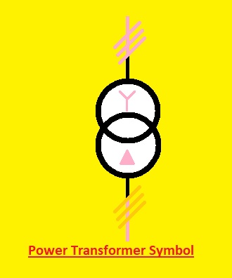
Power Transformer Symbol
- With changes in voltages, this transformer also transfers the power from one circuit to another circuitry. Like the symbol of a conventional transformer, this transformer comes with some more symbol configurations to show the different parameters
- Below is the power transformer’s symbol:
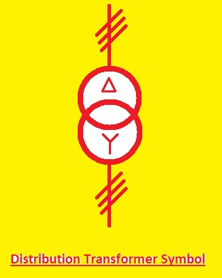
Distribution Transformer Symbol
- The distribution transformer offers final voltage conversion in electrical power distribution system, step down or up voltage of distribution lines to value used by us at homes, buildings. etc
Electrical Transformer Diagrams
Transformer diagrams are symbolization representations of components of a transformer and their connections here you can see different transformers with their electrical diagrams
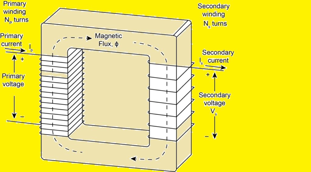
Single-Phase Transformer Diagram
In this transformer, there is separate winding for primary and secondary terminals. Flux flow to the secondary side through a mutual induction process.
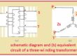
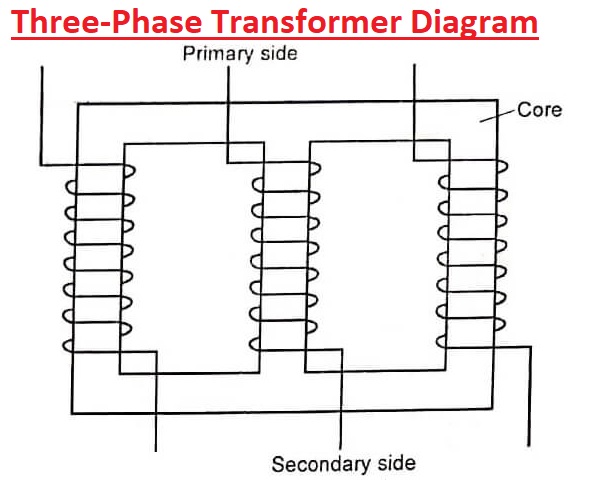
Three-Phase Transformer Diagram
A 3-phase transformer is used to vary voltage of the electrical system with 3 phases. There are different types of connections it has star-star, delta-delta, star-delta, and delta-star.
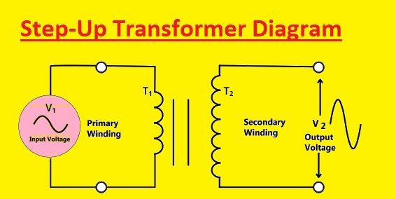
Step-Up Transformer Diagram
It has two winding primary and secondary winding. The voltage at the secondary side is high than the primary side.
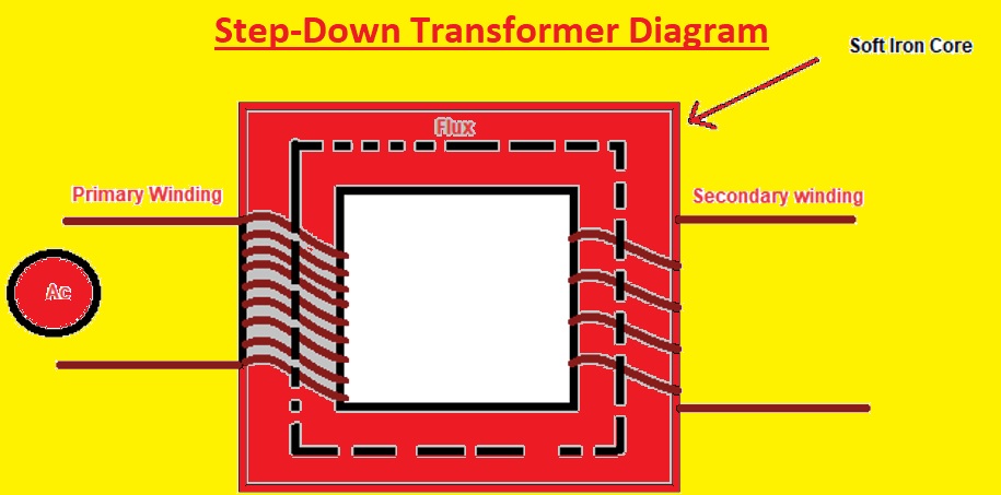
Step-Down Transformer Diagram
This transformer comes with low voltage at the secondary side then the primary side.
What is a transformer used for?
The transformer is used to vary AC voltage levels; the transformer is used to convert the high to low and low to high voltage levels. It is also used to provide isolation between circuits at different stages of signal-processing circuits.
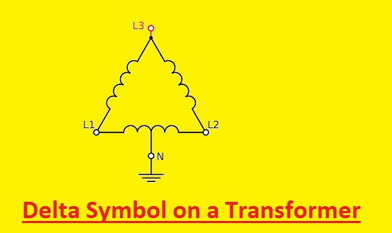
What is the Delta Symbol on a Transformer?
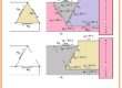
Delta is a permutation and combination of 3 passive components. These 3 passive components can be the same or different. Delta connection is also known as mesh connection. They come in the same connection mode. The delta winding helps 3rd harmonic current to circulate in the transformer and prevents the 3rd harmonic current from flowing in the supply line. Delta-wye transformer provides
30, 150, 210, or 330-degree phase shifts.
Read Also:
- 30 Amp Wire Size: What AWG Wire You Need?
- 125 Amp Wire Size and Breaker Guide
- 60 Amp Wire Size – Which AWG is Best for 60 Amp Breaker
- What Size Wire for 200 AMP Service Underground
- What Size of Wire Do I Need for a 100 Amp Sub Panel?
- How to Replace Doorbell Transformer With Diagrams
- What is Auto transformer Starter
FAQs
Q1. Define transformer, and how does it work?
- The electrical devices that change AC current are called transformers. The transformer operated on the mutual induction principle. Mutual induction is a process through which the current of magnetic flux linked to a coil changes the EMF produced in another coil.
Q2. Write different types of transformers.
- Autotransformers.
- General-purpose transformers.
- Industrial control transformers.
- Isolation transformers.
- Medium voltage control transformers.
- Military transformers.
- Power transformers.
- Step-down transformer.
Q3. What is the purpose of transformer symbols and diagrams?
- The transformer diagram is a standard symbol that is used to denote the types and workings of the different components shown. Magnetic coils can take on different forms, like a choke, a solenoid, an inductor, a winding, or the coils of a transformer with or without a magnetic core.
Q4. How do you read a transformer diagram?
- The magnetic core and 2 windings are the primary and secondary main parts of the transformer diagram. The primary is the input voltage connection, and the secondary is the load connection side.
Q5. What is the importance of understanding transformer symbols and diagrams?
- The understanding of transformer symbols and diagrams is needed that offer correct knowledge of devices to easy understanding of features and different parameters