 Hello, fellows, I hope all of you are having fun in your life. In today’s tutorial, we will discuss What is Faraday’s Law and its practical implementation. The phenomena of electromagnetic induction was explained by Michael Faraday who belonged to England and most of his work was on electromagnetism in 1831. After Faraday Joseph Henry in 1832 who was belonged to America also work on electromagnetic induction. But the final details of this phenomenon was first time published by Faraday, to find this he experimented. He wound to different coils on the opposite side of the ring and connect one wire with the input supply.
He observed that the variation of current in first wire also induce some current and the value of current he found by using a galvanometer. This current production in the second windings was due to flux linking in it that was coming from the first windings. After that, he found some other effect like he finds transient current in a wire when a magnet comes to that wire. In today’s post, we will have a look at work, applications, and some other parameters of this law. So let’s get started with what is Faraday’s Law.
What is Faraday’s Law
- Faraday’s law states that when any conductor is placed in any varying magnetic field the voltage will induce in that conductor.
Emf= dø/dt
- Faraday’s law is the fundamental rule to explain the rule magnetic field in different electrical circuitry.
- In almost every electrical machine either ac machines like an induction motor, induction generator, synchronous motor, synchronous generator, or dc machines as dc motors, dc generators or transformers also follow Faraday’s law of electromagnetic induction.
- For a practical understanding of Faraday’s law, we experiment.
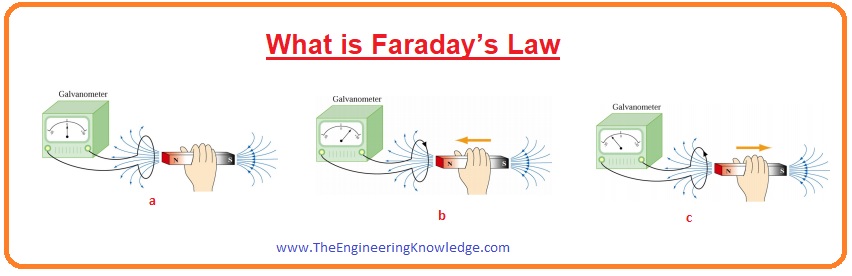
- In the given figure you can observe that there is a bar magnet and a galvanometer, we move this bar magnet and see its flux variation and current production in the galvanometer.
- In the first figure that is denoted as (a) you can see that there is no current value is shown on the galvanometer as the magnet is static.
- In the second figure that is denoted that (b) there is some value of current at the galvanometer it due to the movement of magnet in this case magnet is moving is in the left direction.
- In third figure that is (c) there is again some value of current at the galvanometer but in opposite direction as the now magnet direction towards right.
- From this experiment we can see the practical implementation of Faraday’s Law, when there is variation in flux then the voltage is induced then there is no variation in flux there is no emf induced.
Induced Voltage and Current By Faraday’s Law
- For practical implementation of Faraday’s law and how it generates voltage, we discuss some experiments that will clear your concepts about the Faraday’s Law.
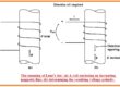
- Let’s suppose that a wire is put in the field of permanent magnet and joined with the galvanometer at the end terminals.
- This is like a closed-loop arrangement. At the start when is there is no movement in the wire zero value of current is shown at the galvanometer.
- If the move changes the position of a loop from left to right voltage is induced in the loop and current shows on the meter. When we stop the loop then the zero deflection at the meter.
- If we move the loop from right to left then there is again current at the galvanometer. But now in the opposite direction.
- The value of the current produced depends on the speed with which we move the loop and its resistance.
- If we change the resistance of loop and then move it in the loop with the same speed then the value of the term (IxR) remains the same with the variation of resistance.
I x R = constant
- It is the induced EMF that causes to produced current in the loop. The value of the current can be increased by doing some factors.
- By increasing the strength of the field.
- Moving loop faster.
- Replacing wire with a large no of turns loop.
- Now we do this experiment differently, we keep the loop static and vary the position of a magnet then there is emf induced in the loop and deflection on the meter screen.
- It is the relative motion between the magnet and the wire loop that generates the voltage induced in the loop.
- It is the value of flux that varies in the loop and produces emf in it. The larger the value of flux variation the there will be larger the emf induced in the loop.
- Now we perform some other experiments for the understanding of voltage induces.
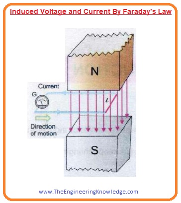
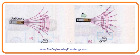
- In the given figure, you can see that the loop is linked to the galvanometer, and bar magnet is placed near it.
- When the magnet is static there is zero current at the galvanometer it is denoted as a in figure and when we move the magnet toward the loop then the current flow through the coil and if we move away magnet from the loop then there is again current produces in the loop. It is denoted as b.
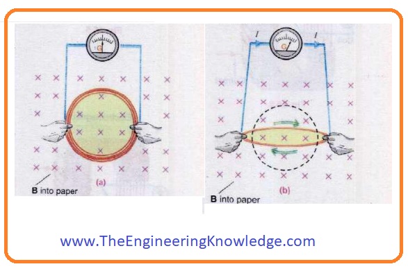
- We do and another experiment for the current production by keeping the value of field constant and varying the area of the loop.
- In figure a you can see that the loop and field both are constant then there is zero value of current at the galvanometer.
- Now if we vary the area of the loop then voltage induced in the loop and deflection shows on the meter.
- The voltage induces till that point the distortion occurs in the loop after that the zero voltage induces in it.
- If we again restore the loop shape in the previous state then there is again voltage induced in it. It is denoted as b in given figure.
- Now we keep the field value constant and the loop area also constant rotates the loop in the field then there is again voltage induced in the loop and some deflection at the meter. It is shown in the figure.
- It is the basic principle of a generator.
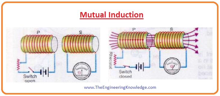
- Now we perform another experiment in which we will see how a flux variation in the first coil induces a voltage in the second coil.
- In the given figure, you can see that there are 2 coils first one is ‘P’ and the second is ‘S’. The first coil is connected to the rheostat, switch, and battery. While the ‘S’ coil is connected to the galvanometer.
- No, if we close the switch of coil ‘P’ then there is current value is shown in the galvanometer of the second meter and then it comes to again zero points.
- If we open the switch again the current is shown at the second coil galvanometer. It is due to the flux variation in the ‘S’ coil current produced, the important thing is that current is only produced when we open and close the switch during this process current in the first coil starts from zero to maximum and then from maximum to zero. Than it flows continuously.
- This phenomenon of flux current generation due to one coil in a second coil is called mutual induction. The working of the transformer relies on this principle.
Faraday’s Law Application
- These are some applications of Faraday’s Law that are described here. It is mostly employed in industrial machines and medical equipment construction.
- The working of transformer follows the Faraday’s law of electromagnetic induction.
- Generators also follow this principle.
- The induction cooler operation also relies on the working of Faraday’s law.
- Some musical instruments also follow this law such as electric guitar.
FAQs
What is Lenz’s law and Faraday’s law?
- Lenz’s law defines the direction of induced current and Faraday’s law is based on the magnitude of induced back EMF with the rate of change in inducing a magnetic field
What is the general formula for Faraday’s law?
- The Faraday law of induction defines that magnitude of emf induced in the circuit is proportional to the rate of change with the time of magnetic flux Φ across the circuit emf = −dΦdt.
What is Maxwell’s law of induction?
- Maxwell’s 3rd equation was obtained from Faraday’s Law of electromagnetic induction. it defines that when there are n turns of conducting coil is closed in closed path put in variable field EMF forces induced in coils.
So friends that is the detailed post about Faraday Law I have mentioned each and every parameter related to Faraday law. If you have any queries about this law ask in comments. See you in the next post. Have a good day..