 Hello, readers welcome to new post. In this post, we will have a detailed look at Three Phase Transformer Windings Connections. The transformer is the very basic component of the power system that used to vary the voltage values according to the system needed and uses. A three-phase transformer is generally employed at the generation end or high rating power station where large voltage to be step down.
Normally three windings are wounded at three cores for a three-phase transformer. There is different connection techniques are used to make the link between these windings for current flow and the system needed. In this post we will learn about the different connection used in the transformer and their voltage values and current according to design arrangements. SO let get started with Three Phase Transformer Windings Connections.
Three Phase Transformer Windings Connections
- Normally three transfer of single-phase arrangements are linked in such fashion that 3 windings having same voltage values are linked in delta and other three of similar voltage values in wye connection.
- This type of configured for transformer called delta wye or wye-delta.
- Ther is another choice for connection is wye wye or delta delta.
- If in these 3 single-phase transformers there are 3 windings primary secondary and tertiary then two windings can be linked in y design and other in delta and 2 can be in a delta configuration and third one y.
- In place to use three separate transformers, there is one transformer having three windings at the single-core can be constructed.
- The use of a single-phase is cheap and losses also reduce.
- If a fault occurs then we have to change just a single unit than three single-phase units.
- IF fault in the delta delta bank arrangement
- If a failure occurs in a delta delta configured single-phase we will change it other two will be operated and supplying the load
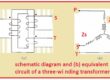
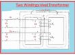
- In case of single-phase transform we can write doted at each endpoint of every coil denoted end can be defined H1 for high volts coil and X1 for low volts coil.
- The opposite point will be denoted with H2 and X2
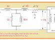
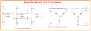
- The above diagram showing 3 single-phase transformers linked in a wye connection.
- In the circuitry capital letter X, Y, Z denoting high volts end and small letter x, y z denoting low volts points.
- Hig volts points are denoted with H1 H2 and H3 and less volts with Y1, Y2 and Y3.
- In case of wye to wye or delta to delta transformer voltage to neutral terminal H1, H2 H3 are in phase to the volts to neutral points denoted with Y1, Y2 and Y3
- The circuit shown in the above figure gives the same detail about a transformer.
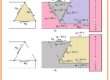
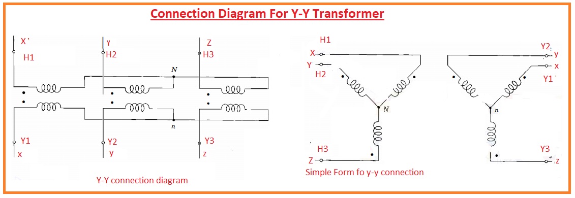
How to Transfer ohmic Parameters of per phase impedance of one side of a three-phase transformer
- In the below diagram, a different connection configuration of transformer is shown with the per phase impedances transformer from one side to another.
Y-Y Connection Per phase Impedance Transfer
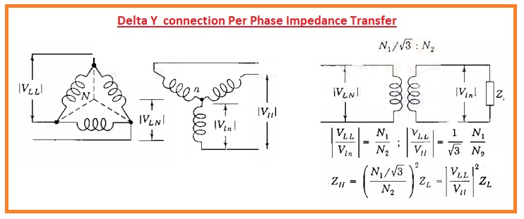
Delta Y connection Per Phase Impedance Transfer
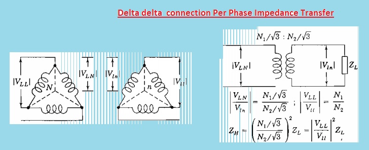
Delta delta connection Per Phase Impedance Transfer
Why a delta-wye transformer connection?
- Delta wye transformer connection is used for a three-phase transformer. The secondary winding of the Y connection helps connect a single-phase load to a distributed neutral line for three phases, and the delta connection is configured on one winding.
How many windings are in a 3-phase transformer?
- The 3-phase transformer comes with 6 windings, 3 primary and 2 secondary. The primary and secondary windings are connected in different arrangements to fulfill the different designs. The windings are connected in a Delta” or “Wye configuration.
What is the star-delta connection of a three-phase transformer?
- The star-delta connection is a certain technique employed for starting a 3-phase AC transformer, especially for handling high starting current that can become 5 to 7 times the rated current in high-power devices.
What is the difference between delta connection and Y connection?
- The delta connection Connect coils in an equilateral triangle and apply single phases at vertices. The wye connection connects one endpoint of every winding and uses single phases to open points. These two connections provide different results if power is provided.
Why a 30-degree phase shift in a transformer?
- The 30-degree phase shifts exist between the output of the delta and Y secondary. This transformer design causes triplet harmonics for canceling primary and non-triplet cancel in the secondary.
Why is DyN11 used in transformers?
- Dyn11 denoted transformer with delta connected HV winging and star connected LV winding. It provides flexible voltage transformation and is good to use for applications where high voltage step-up or step-down is needed.