 Hi readers welcome to the new post. In this post, we will have a detailed look at Introduction to Three Phase Transformers. The transformer is a device employed in a power system to increase and decrease power levels according to system requirements. The working principle of transformer is based on the Faraday law that says rate of change of flux in conductive body induce voltage.
There are different types of a transformer according to structure and voltage level changing, In this post, we discuss the three-phase transformer that generally used at the generation side to transmit high-level voltage at a larger distance. So let get started with Introduction to Three Phase Transformers.
Introduction to Three Phase Transformers
- Normally there are three-phase systems of ac is used at the generation and distribution of electrical systems. 3 Phase system has become the most important part of the current system
- So the operation of transformer is compulsory to understand the system.
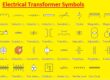
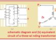
- There are 2 methods to construct the 3 phase transformers. In first method, the transformer is just linked to the system.
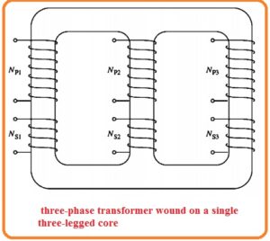
- In 2nd technique for the creation of this transformer wound 3 sets of windings made with the copper to the single-core.
- In below figure you can see these 2 types of transformer configurations.
![]()
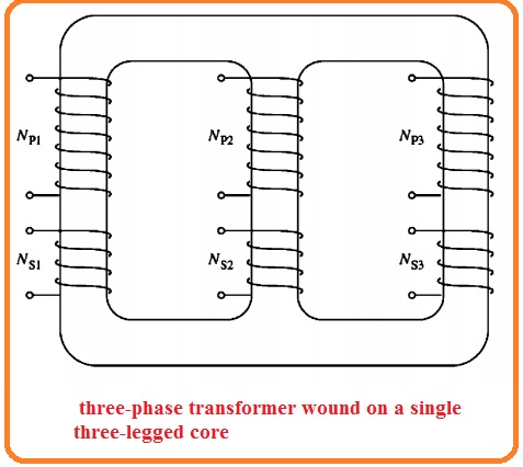
- The assembly of a single 3 phase transformer is used currently as it has less weight small size and less expensive.
- In ancient time tranformer construcioon based on conneciton of 3 distinct tranformer.
- This technique offer a benefit since if any fault occurs in one transformer that can be separated from the system easily.
- Still, in the different systems, there is three single-phase transformers are employed in the system.
Winding Connection of Three-phase Transformer
- The 3 phase transformer comprises of 3 transformers some are separation configuration and some in single-core configuration.
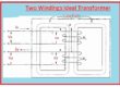
- The 2 ways through which primary and secondary windings are linked first one i delta and the second one is wye.
- So there are 4 ways of connection among these windings.
- Wye-delta (Y -Δ)
- Delta-delta (Δ-Y)
- Wye-wye (Y-Y)
- Delta-wye (Δ-Y)
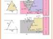
- This connection configuration can be seen in below figure.

- The way to discuss 3 phase transformer is to see the configuration of a single-phase transformer.
- The impedance efficiency voltage regulation and other measurements in case of 3 phase transformer are found according to per phase system with the use of a similar method that used for a single-phase transformer.
- The benefits and drawbacks of every category of 3 phase transformer can seen here
WYE-WYE CONNECTION COnfiguration
- The Y Y connection configuration of 3 phase transformer can seen here.
![]()
- In this arrangement, primary side voltage of every phase of transformer is mentioned here.
- VθP=VLP/√3
- The primary side voltage is correspondent to the secondary side voltage through turn ratio of the transformer.
- The voltage at secondary winding is correspondent to the line voltage of secondary through VLS=√3Vθs
- So total voltage ratio for this connection arrangement is mentioned here.
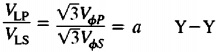
- There are 2 main drawbacks of this connection arrangement.
- If load of the transformer circuitry arrangement is not balanced in result voltage at the phase of the transformer are also not balanced.
- The second is that 3rd harmonic voltage can be very high.
- If 3 phase set of voltage is given to the Y-Y configuration of the transformer the voltage at any phase are one twenty-degree different from any other.
- So 3rd harmonic element of every one of the 3 phases will be in phase to one another.
- AS there are 3 cycles in 3rd harmonic for every cycle of the fundamental frequency.
- So there is 3rd harmonic elements exist in the transformer since the nonlinear behavior of transformer core and these elements will be added
- The consequence is a very high 3rd harmonic element of voltage at upper of fifty to sixty-hertz fundamental voltage.
- These 3rd harmonic voltages are large than the fundamental voltage
Transformer with PCB Project Simulation
- After getting a deep understanding of the three-phase transformer and its configured circuitry. You must have to make a project where you will use this transformer as a voltage varaibel device that will help to run your project and all its components.
- The creation of all projects through electrical and electrical engineering are generally assembled on the PCB board. That is considered as the main component of any device and project.
- So to use PCB for your projects with transformer and another component you must has to buy the board with good quality and reasonable prices.
- That will be difficult for you to get the PCB assembled with high-quality production and project simulation.
here I want to resolve your queries about the PCB creation board for your projects. I suggest the best PCB manufacturer and projects creator that is one and only PCBWAY. - They are providing the high-quality PCB board at reasonable prices they not only provide PCB board but also offered the services related assembly of projects that you are making.
- for this, you just have to send the details of your board dimension and related parameters to their engineering and technical team they will give a detailed overview of your board and will guide you how to make it with good quality and affordable prices.
- With that, they also come with services to students and engineers to introduce their projects to their community where different projects are upload to the engineering community.
- Through their projects sharing facility, you just not share the project but can get the ideas of new projects that are offered by the other members.
- By offering the projects sharing feature they also help the students to make new projects through their sponsorship program.
- So all in all if you are getting to make the new projects with the use of a transformer you must visit this project coordinator and PCB supplier they will guide you with all aspected of your projects.
How to eliminate 3rd harmonic
- There are 2 methods to remove the unbalance and 3rd harmonic issue.
- Grounded the neutral wire of transformer specialty the primary side neutral. This connection allows the addition of 3rd harmonic elements to results the current movement in the neutral in place of creating large voltage.
- The neutral also offers the returning way for current that in balanced in the load.
- To the addition of 3rd wining connected in delta configuration with the transformer bank.
- In results the 3 harmonic components of voltage will be added in results the circulating current move in the winding.
- Due to that 3 harmonics will diminish like the grounding of neutral.
- The delta configured tertiary winding not to remove the third harmonics bt also used to provide energy to the substation where it employed.
- The size of tertiary is is such that so it can handle circulation current so it constructed with the 1/3 of power rating ot 2 other windings.
Transformer WYE-DELTA CONNECTION Configuration
- The tye delta configuration of 3 phase transformer can seen here.
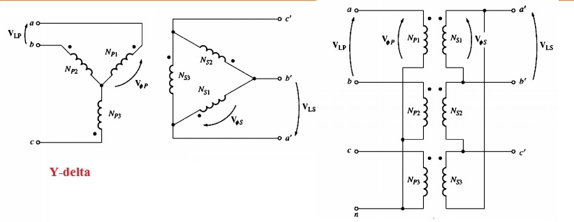
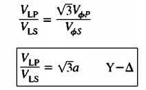
- In this arrangement, the primary voltage is correspondent to primary phase voltage through VLP=√3Vθp But the secondary voltae is like to the secondary phase voltage.
- VLS=Vθs
- Vθp/Vθs=a
- Therefore the net relation among the line voltage at primary of bank and line voltage at secondary of bank is mentioned here.
- The wye-delta connection offer zero problems related to 3rd harmonic element because they are used in circulating current at delta arrangement.
- The connection is also stable according to an imbalance of loads the delta distributed the existence of imbalance.
- The configuration offers the issue since the connection at secondary voltage is moved thirty-degree according to the primary voltage of the transformer.
- The factor that phase shift exists can result in an issue in parallel configuration of secondary of 2 transformer banks at same time.
- The phase angle of transformer secondary should like to parallel that indicates that there should be attention given to the direction of thirty-degree phase shift existing in every transformer configured in a parallel configuration.
- In the US it is necessary to create the secondary voltage lagging the primary with an angle of thirty degrees.
- Though these is standard measurements it not always considered
Transformer DELTA-WYE CONNECTION Configuration
- Delta wye configuration of 3 phase transformer is can seen here
- In this arrangement, the primary line voltage is equal to the primary phase voltage VLP = VΦp
- The secondary side voltage are correspondent through VLS = √3VΦs so the line to line voltage ratio of transformer connection is mentioned here.
- The connection has similar drawbacks and similar phase shifts like wye to delta transformer. The connection can see in above figure creates the secondary voltage lagging the primary voltage through thirty degrees
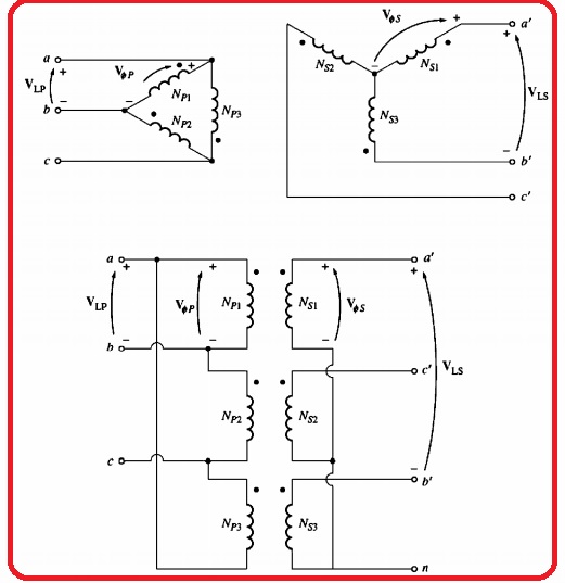
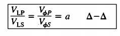
Transformer DELTA-DELTA CONNECTION
- The delta delta configuration is shown here.2.38d
- In this arrangement VLP=VΦp and VLS = VΦs in a result, the relationship between primary and secondary winding is shown here.
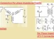
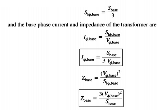
Three-Phase Transformers Per Unit System
- The per-unit system of calculation is also applicable for both single-phase and three-phase ttransformers
- The equaion aer mentieond here.
That is all about three-phase transformer if you have any further query ask in the comments. thanks for reading have a nice day.