![]() Hello, readers welcome to the new post. In this post, we will have a detailed look at Introduction to Ideal Transformer. The transformer is an electrical device that used to vary the voltage level in the system from high to low or low to high according to system and load requirements. During this process, different losses occur in the transformer. Such a transformer that has zero value of losses that occur in the practical transformer is called an ideal transformer.
Hello, readers welcome to the new post. In this post, we will have a detailed look at Introduction to Ideal Transformer. The transformer is an electrical device that used to vary the voltage level in the system from high to low or low to high according to system and load requirements. During this process, different losses occur in the transformer. Such a transformer that has zero value of losses that occur in the practical transformer is called an ideal transformer.
The main losses that do not exist in the ideal transformer are core, copper losses, eddy current, and hysteresis losses. The output efficiency of these transformers also a hundred percent. In this post, we will discuss its working, circuit diagram application, and other related parameters.So let get started with Introduction to Ideal Transformer.
Introduction to Ideal Transformer
- There are normally two windings are wounded in a transformer in the normal way and in certain cases has 3 windings that are linked magnetically.
- In case of a power transformer, there is windings are positioned at the core created with a core that helps to make confinement of flux in the transformer and complete linking to the other windings.
- Numerous windings are joined in the transformer to make a single set of coils.
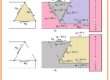
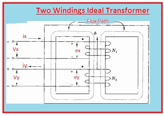
- In the below diagram, we can see that 2 windings are posited at the iron core to create a shell-type transformer of a single-phase configuration.
- The turns in the coils have larger numbers from many hundreds to many thousands according to system requirements.
- For practical understanding, we suppose that flux changes in sine waveform in the transformer core and transformer has ideal configuration that gives two main points.
- Core has infinity value of permeability and second is the total flux in the transformer is moving in the core that mean zero value of leakage flux.
- Also core and windings losses are 0
- The voltage ex and ey will be produced through varying the flux has value same to the terminal voltage of transformer Vx and Vy
- The voltage ex and ey are in phase configuration when indicated through negative and positive signs.
- If we apply Faraday law then we have.
Vx=ex=N1dθ/dt
Vy=ey=N1dθ/dt
- θ is denoted the value of instantaneous flux and N1 and N2 are numbers of the transformer.
- According to above circuitry, the direction of flux for first windings is positive according to Righ hand rule that says if winging is grasp in such way that figure shows the direction of current thumb will indicate the direction of flux.
- Now we have
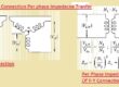
Vx/Vy=Ex/Ey=N1/N2
- In some cases, someone do not the direction of windings wounded for this purpose use dot to indicates the positive side of windings
- Dots are can be seen in above circuitry.
- Here can be noted that similar output is got through putting the dots therefore current passing from dot point to non-doted point of every coil generates mmf operating in the similar side in the circuitry.
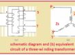
- In below circuitry, the schematic of above transformer can.
![]()
- For determining the values of current ix and iy we use ampere law then we have.
- that define that current about the closed-loop is mentioned here.
![]()
- I denoted the current in the closed-loop
- H is magnetic intensity
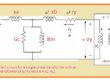
- After applying this rule to the above circuitry for two closed paths we have.
![]()
- The minus sign will be replaced to plus if a direction is reversed for current iy
- In case of infinity permeability intensity of the field will be 0
- If flux density is finite then emf induced will be finite in the results we have.
N1Ix=N2Iy=0
Ix/I2=N2/N1
- If impedance is linked to the windings second of circuitry than we have.
Z=Vy/V1
That is all about the Introduction to Ideal Transformer if you have further query ask in comments. Thanks for reading have a nice day.