![]() Hello friends welcome to new post. In this post, we will have a detailed look at Single Phase Transformer Equivalent Circuit. The transformer is an integral part of our electrical system that used to vary the voltage values from step up to step-down conditions according to load requirements. The transformer that works at the single-phase is called the single-phase transformer and normally has two windings in the system.
Hello friends welcome to new post. In this post, we will have a detailed look at Single Phase Transformer Equivalent Circuit. The transformer is an integral part of our electrical system that used to vary the voltage values from step up to step-down conditions according to load requirements. The transformer that works at the single-phase is called the single-phase transformer and normally has two windings in the system.
In this post, we will learn about the circuit of a single-phase transformer and its different parameters. So let get started.
Single Phase Transformer Equivalent Circuit
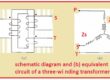
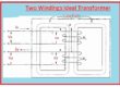
- The circuitry shown in the below figure is the circuitry configuration of a normal practical transformer.
- There is 3 main lack points in this system, first of all not show the transformation of current and voltage second, there is no separation between primary and secondary sides and third, there is no core losses.
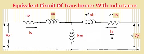
- If we apply input sine wave voltage at the primary side of this practical transformer at the iron core and its secondary is open-circuited the less value current denoted IE called exciting current will move in the circuitry.
- The main element of the above circuitry is magnetizing current that is related to current passing in the Bm that is magnetizing susceptance.
- The magnetizing current is generated in the flux at the core of a transformer.
- The current IE that has very fewer values is not taken into consideration for iron losses produce the magnetizing current leading with ninety degrees and not indicated in the above figure
- There is the existence of core losses due to the variation in the direction of flux when energy is lost due to heat and this loss are called hysteresis loss.
- Due to a change in flux circulation current is generated in the core and that current caused to produce copper losses also called eddy current
- Eddy current losses can be minimized through the lamination of the core.
- In case of the secondary side is an open circuit then its primary is operating like inductance having a very large value.
- In the case of the equivalent circuit, IE is not ignored as in above circuit. It takes into consideration by making circuit having conductance Gc with Bmin parallel combination.

- If the design of the transformer is accurate then the maximum flux density of the core exists at the knee point of B-H.
- In result, there is no linear behavior between flux density and field intensity.
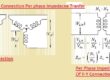
Single Phase Transformer Per Unit Impedance
- The ohmic parameters of resistance and leakage reactance of rely on at the measuring side of the transformer mean either these values are found at high or low voltage windings of the device.
- If they are measured in per unit then base KVA is a rating of transformers
- The base volts will be low windings voltage rating if resistance and leakage reactance are referred to the side of the low winding.
- If these terms are referred to the high voltage side then bae volts are the voltage rating of the transformer.
Read also
- How to Replace Doorbell Transformer With Diagrams
- All Types of Electrical Transformer Symbols and Diagram
- Difference Between Current Transformer (CT) & Potential Transformer (PT)
- Difference Between Power Transformer and Distribution Transformer
- Where is the Doorbell Breaker Located? Easy Way to Findout
That is all about the Equivalent circuit for a single-phase transformer if you have any further query ask in the comments, Thanks for reading have a nice day