 Hello, readers welcome to the new post. Today we will discuss the Dual Power Supply Circuit. The dual power supply is dc power supply that has two outputs positive and negative. Its main operation is to provide constant power to the circuit without any damage to the system. In numerous electronic devices and circuits, there is a need for a DC power supply. The use of a dual power supply helps to operate the electronic and electrical devices installed in the circuit.
This power supply has positive and negative potential with a ground point. Some electronic projects consist of transistors that use a dc power supply. Such as the circuit of tube amplifiers dc volts required to the plate control grid and screen. With that biasing or transistors also needed dc power. There is a need for dual power sources for operational amplifiers.
If you are new to this project and have fewer sources related to electronics for project creation must have need experts like PCBWAY.
This PCB supplier provides a high level of PCB services with great quality. You can get PCB prototyping services for just five dollars for ten pieces and with dimensions of 100 x 100mm also have the feature of FR4 double-side custom PCB. They come with 9 solder mask colors white or black silkscreen and any range of thickness (0.6mm, 0.8mm, 1.0mm, 1.2mm, and 1.6mm; thicker and thinner PCBs can get from PCBWAY but will increase the price. The default min track/spacing value is 6/6 mil but tolerances of up to 4/4 can get at a premium. There is default min hole size is about 0.3mm but with the enhanced feature can also get it.
PCBWay always supports the development of the open-source community and sponsored Open Source Hardware.. To help electronic enthusiasts better communicate with each other, you can share your PCB design in the PCBWay community and vote for the most popular PCB design. If others like your design and place an order, you can earn a 10% commission.
They recently introduced the PCBWAY plugin in KiCAD software that will help you make your PCB design but also helps to get easy PCB services from PCBWAY with just one click. That has resolved all problems to find the PCB manufacturers. After making the design just move to that plugin and order at PCBWAY

Introduction to Dual Power Supply
- The dual power supply is the power source that provides two different volts at the output with a single input.
- It comes with different circuit configurations but commonly used are two different or two same outputs with different polarity.
- In a circuit like high power operations in industries needed two power sources. First regulation and noise five volts supply that is used for controlling the small devices like microcontrollers and digital signal processors. The second one is used for control of the motor and switching.
- That dual power supply is used for analog signal processing and amplifier circuit-like audio devices. A circuit having positive and negative outputs is preferred for processing and transformation of analog signals through the use of analog to digital converter
- A circuit having fewer power needs can be operated through a single power supply by making a connection to the divider circuit.
Importance of Dual Power Supply
- There is a need for varied bipolar output volts for operational amplifiers. One is positive and the second one is negative. This circuit comes with two rails. Therefore to operate the operational amplifiers there is a need for a dual power supply
- If we have a circuit that has to operate on a single power supply without any distortion there is a need for a dual power supply. So if one circuit has an error we can remove it and repair it without removing the other circuit.
- A DIY circuit such as a mobile phone charger, and power bank circuit also uses a dual power supply
Dual Power Supply Circuit

Component of Project
- The component used in this project is listed here.
- Step Down Transformer
- Capacitors
- Voltage Regulator
- Diodes
- Buck Strip
- Resistances
- LED
- PCB by PCBWAY
Circuit Construction

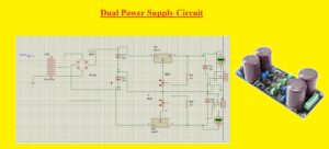
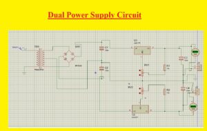
- First of all, make the bridge circuit through the use of diodes. The bridge circuit is used to convert the ac input supply to dc that will be converted to output volts.
- This rectifier is connected to the output of the step-down transformer and the output of the bridge is linked to voltage regulators.
- The capacitor of 100nF is attached to the input regulators
- At the output terminals of regulators, there is voltmeters are connected where we can get the output.
Circuit Working
- There are four main parts of this circuit
- Transformer
- Filter
- Regulator
- Rectifier:A rectifier is an electrical circuit that converts alternating current to direct current. The process of converting alternating current to direct current is called rectification. There are many categories of diodes, some of which were used in the previous year, such as vacuum tube diodes, mercury arc valves, etc.Currently, semiconductor diodes are used as rectifier circuits. There are many applications of rectifiers, but they are most commonly used in a DC power and transmission system that transmits DC high voltages. There are 2 main types of rectifiers, the first is the half-wave rectifier and the second is the full-wave rectifier. A half-wave rectifier converts the positive cycle of alternating current to direct current, and its circuit consists of a single diode. A full-wave rectifier converts a full cycle of alternating current to direct current and its circuit uses 2 or 4 diodes for rectification. The output obtained by these filter circuits is not pure DC and has some ripple to be pure DC and smooth different filter circuits are used.
- At the input of the circuit, there is 230V Ac is connected which is stepped down to 5 V AC through the use of a step-down transformer.
- Ac now we have AC at the input transformer but we need dc so these volts are given to the rectifier that will transform that volt to dc.
- These dc volts are not pure dc and have some ripples so capacitors work as filter circuits and make pure dc by removing the spikes in volts.
- After that these volts are provided to voltage regulators that are LM317 and LM337 that regulate this pure dc to output values
- With that some other voltage regulators can be used like 7812, 7912 normally 78XX series of volts is used for positive supply and 79XX provides the negative volts
Dual Power Supply Applications
- The main applications of dual power supply are discussed here
- It used in power bank circuits
- Cell phone charger has this circuit
- It is part of 12 vols battery charger
- The direction of the dc motor can be controlled through this source
- It also used in audio amplifiers
- Operational amplifiers and power amplifier
That is all about the Dual Power Supply Circuit all details has explained that will helps you to make the dual power supply for your projects.


