![]() Hello, readers welcome to the new tutorial. In this post, we will have a detailed look at Three-Phase Transformation using two Transformers. The transformer is an electric instrument that is used to vary the voltage level. In a three-phase transformer, there is three windings are used to transform three voltages.
Hello, readers welcome to the new tutorial. In this post, we will have a detailed look at Three-Phase Transformation using two Transformers. The transformer is an electric instrument that is used to vary the voltage level. In a three-phase transformer, there is three windings are used to transform three voltages.
There is wye and delta configuration is used to transform of voltage. So let’s get started with a Three-Phase Transformation using two Transformers,
Three-phase transformation using two Transformers
- For 3 phase transformer connection configuration, there is a technique to do 3 phase transformation with the use of 2 transformers.
- These methods do these operations cause decrement in the power managing ability of transformer but they can be discussed through different conditions.
- The connection arrangement used for 2 transformers is mentioned here.
- The open delta. (or V- V) connection
- The Scott-T connection
- The open-Y -open-.delta. connection
- The three-phase T connection
Let us discuss these connections one by one with the details.
Open Delta (or V-V) Connection
- In certain conditions, the complete transformer bank is not employed for the construction of a three-phase transformation.
- For instance, suppose that delta delta transformer bank consists of a distinct transformer that has faulted phase which should be eliminated for construction.
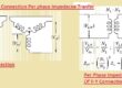
- The resultant condition can see here.
![]()
- If 2 secondary voltages have values VA = V∠0 and VA = V∠120° Volts so values of voltage about the gap here 3rd transformer is employed is mentioned here.
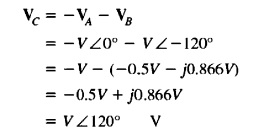
- It is a similar voltage that will exist if 3rd transformer is used. Phase C is known as ghost phase. So the open delta configuration caused the transformer bank to obtain through the usage of 2 transformers causing power to move to last when fault eliminated.
How much apparent power can the bank supply with one of its 3 transformers eliminate?
- First of all it looks that it can deliver 2/3 of the rated apparent power. Because 2/3 of the transformer is using in the system.
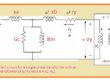
- It does not look a simple state. To observe the result when the transformer is eliminated observe below figure.
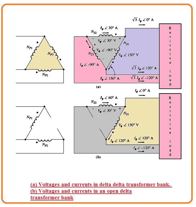
- The above diagram denoted by a transformer, bak is operating in normal condition linked with the resistance load
- If the rated voltage of a single transformer in the bank Vθ and rated current is Iθ and highest power given to the load is mentioned here.
- P = 3VθIθcosθ
- The angle between current and voltage is zero
- P = 3VθIθcosθ
- P = 3VθIθ
- The open delta transformer can seen in the above figure denoted as b.
- it is significant to observe the angle at voltage and current in the transformer bank. Since one transformer phase does not exist the transmission line current has the same value to the phase current in every transformer and the current and voltage in the transformer bank differ in angle through thirty degrees.
- As the current and voltage angle are different in every transformer. it is compulsory to observe every transformer on a single basis find the extreme power that can be provided to it.
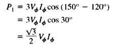
- For transformer one the voltage has an angle of one fifty degrees and the current has an angle of one twenty degrees. Therefore equation for extreme power in the first transformer is mentioned here.
- In case of the second transformer, the voltage has an angle of thirty degrees and current at an angle of sixty degrees therefore extreme power is
![]()
- So the net extreme power of open delta bank is given here.
- P = √3VθIθ
- The rated current has a similar value in every transformer whether that are 3 or 2 and voltage is like at every transformer, therefore, ratio of output power exist through the open delta bank to the output power through the general 3 phase bank is mentioned here,
![]()
- The existing power through open delta bank has a value of 57.7% of real bank value.
- Here question arises
- What will affect at the other open-delta bank’s rating?
- With that the net power which the 2 transformers can generate is 2/3 of the original bank rating. For finding observe the reactive power of open delta bak.
- The reactive power of first transformer given here.
![]()
- So the transformer is generating reactive power that the other is using. That is energy transformation among the 2 transformers 3 phase which restricts the power to 57.7% real bank values in place of expected value 66.7%
- The other method to observe the rating of open delta connection is 86.6% of rating the 2 other transformer
- Open delta connections are employed rarely when it is needed to provide less quantity of 3 phase power to single-phase load.
- In this condition, the connection can seen here.
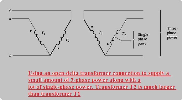
- Here transformer denoted as T2 is higher than other
Open-Wye-Open-Delta Connection
- The open wye open delta connection are like to the open delta connection configuration with the difference that primary voltage are operating through 2 phases and neutral winding.
- open wye open delta connection can see here.
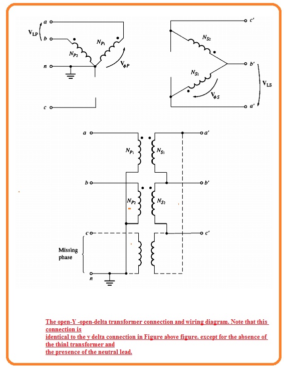
- It is operated to run less usage required 3 phase operation in distant places where 3 phase does not exist at power poles.
- For this connection arrangement, the user can obtain 3 phase operation makeshift configuration till the required installation of 3rd phase at power poles.
- The drawback of this arrangement is that a high returning current should pass in the neutral wire of the primary circuitry.
Scott-T Connection Configuration
- The Scott T connection is a method to operate 2 phase existing ninety degrees through 3-phase supply.
- In previous times ac supply transmission 2 phases and 3 phases of power networks were mostly used.
- That time it was compulsory to join 2 and 4-phase power networks and scott t transformer arrangements was created for this work
- Currently, 2 phase power is used to control operations. butt Scott T is now employed to generate the power required to run that.
- The Scott T comprises of 2 one-phase transformers having same rating values.
- On consists of the tap at its primary side with 86.6 % of full-load voltage. 1
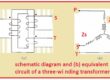
- Can seen in below figure denoted as a
![]()
- The 86.6 % tap of transformer T2 is linked to the center tap of transformer T1. The voltage given at the primary coil can seen above figure denoted as b, while the resultant voltage given at the primary site of this transformer can be seen in the above figure denoted as c.
- As these voltages are ninety-degree separated the outcomes in 2 phases,
Three-Phase T Connection
- The Scott T connection are employed 2 transformers to transform 3 phase power to 2 phase power at different voltage values.
- Through a normal variation in the connection, the similar 2 transformers can transform 3-phase power to 3 phase power for values.
- These connections can seen here.
![]()
- In this configuration, the primary and secondary windings of transformer T1 exist tapped 86.6 % and this tap are linked to the mid tap of resultant coils of transformer T1.
- In this arrangement, T1 is known as the main transformer and T2 teaser transformer
- in the Scott T configuration, 3 phase input voltage generates 2 voltage ninety degrees separated at the primary winding of the transformer.
- This primary voltage generates a secondary voltage that are separated through ninety degrees.
- The main benefit of 3 phase T connection than 3 phase 2 transformer connection is that neutral wire can be linked to the primary and secondary sides of the transformer bank
- This connection arrangement is used in self confined 3 phase distribution transformers because its structure price is less than 3 phase transformer bank
2 phase to 3-phase transformer
- Transformer the 2-phase supply into DC and uses a three-phase inverter to converter to dc supply into 3 phase ac
3 phase to 2-phase transformer
The Scott-T Connection technique is used for connecting 2 single-phase transforms to make a 3-phase to 2-phase conversion. . Scott connection of transformer also called T – T connection. In this configuration, two transformers are connected electrically not magnetically
Read also:
- How to Replace Doorbell Transformer With Diagrams
- How to Connect Doorbell Transformer Wiring Diagram
- What is Auto transformer Starter: Working & Its Applications, diagram,advantages
- Three-Phase Transformation using two Transformers
- Introduction to Three Phase Transformers
- Power Transformer Faults and Protections
FAQS
Can you get 3 phase power from 2 transformers?
Not it can not be done. Open delta configuration that helps to use 2 single phase transformers to step down voltages of high value 3 phases o low 3 phase one
What is a 3-phase to 2-phase transformer?
A Scott-T transformer or Scott connection is used to generate two pashes power from three-phase source,
How to wire 2 single-phase transformers for 3-phase?
For this open delta configuration can be used. there are two transformers used and it can provide 58 percent power of a standard delta-connected three-phase transformer.
To make an open delta configuration of two follow these points
- Make a parallel combination between two primary winding transformers
- Secondaries of the transformer must be in series
- Make center tap of one secondary winding with neutral of load
How can a three-phase transformation be accomplished using only two transformers?
- With the use of one wire and connect it with the primary of both transformers. Wire every other wiring with two remaining primary terminals. On the secondary, connect one wire from each primary with the each other. Now we have 3 phases on secondary.
What type of three-phase transformer connection uses only two transformers?
- The open delta or V connection needed two transformers for providing 3 phase power as compared to the standard delta connection uses 3. The transformer operated on a principle where turn ratio defines voltage ratio, and construction normally comes with a wound on a ferromagnetic core.
Is there a two-phase transformer?
- Two-phase transformer is used for a two-phase supply when there is to change voltage value of the two-phase supply then use two-phase transformer. But normally it is not used, a single or three-phase transformer is used.
What is the difference between 2-phase and 3-phase?
- Three-phase power needed less conductor mass for the same voltage and overall power than two-phase 4-wire circuits of the same capacity. it replaced two phases of power from the distribution of energy but two phases circuits are used in control systems.
Why 3 phase AC is used but not 2-phase?
- 3 phase electric wire needed less conductor mass for same voltage and overall power, thatn 2 phase 4 wire system of same capacity. it
That is a detailed post about Three-Phase Transformation using two Transformers if you still want ot get about this topic ask in the comments.