Table of Contents
ToggleWhat is the electrolytic capacitor symbol?
Electrolytic capacitors are types of capacitors known as polarized capacitors that have an anode or positive plate created with the use of metal that makes an insulating oxide layer through an anodization process.
The oxide layer works as the dielectric of the capacitor. Solid, liquid, or gel electrolytes cover the surface of the oxide layer, working as a cathode or negative plate of the capacitor.
They have thin dielectric oxide and larger anode surfaces, which make these capacitors capacitance-voltage multiple unit volumes than ceramic or film capacitors and come with larger capacitance values. In this post, we will have a look at Electrolytic capacitor symbol & working.
Introduction of Electrolytic Capacitor Symbol
The electrolytic capacitor is a capacitor that uses electrolytes to get larger capacitance than other capacitor types.
The electrolyte is liquid or gel and comes with a high concentration of ions. All electrolytic capacitors are polarized, which means that the voltage on the positive terminal is higher than the voltage on the negative terminal.
It also comes with a larger leakage current, equivalent series resistance, and limited working life.
It can be a wet electrolyte or solid polymer. It is made with the use of tantalum or aluminum.
Supercapacitors are special types of electrolyte capacitors called double-layer electrolytic capacitors and have capacitance values of 1 µF to 47 mF.
Aluminum capacitors are used in power supplies and computer motherboards. As they have a polar nature, they can also be used in DC circuits.

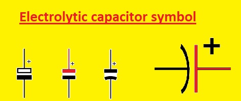
Electrolytic Capacitor Symbol
- Polarized capacitor electrolytic capacitor comes with a plus sign + which is an anode symbol and curved line denoting the negative plate and a straight line denoting the positive plate.
Working Principle of Electrolytic Capacitors
The electrolytic capacitor is made asymmetrically and comes with polarized components. This structure provides high voltage, and one side gets more power than the other.
It has a metallic or aluminum anode with an oxidizing cover layer that works as a dielectric, and it is a positive electrode of the capacitor. It gets input voltage.
The cathode, which comes with aluminum foil and liquid electrolyte, works as the negative electrode. This liquid is made with the use of water and sodium borate or boric acid.
Some sugars are used to avoid evaporation. Aluminum oxide is used for the polarity of electrolytic capacitors. It is positioned through an electric field. If DC is given to an electrolytic capacitor, it must use accurate polarity.
Connect the positive terminal with the positive lead and the negative with the negative lead.
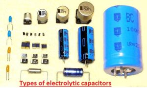
Types of Electrolytic Capacitors
- There are three main types of electrolytic capacitors listed here.
- aluminum electrolytic capacitors
- tantalum electrolytic capacitors
- niobium electrolytic capacitors
Aluminum Electrolytic Capacitor
- These capacitors come with an aluminum anode, an aluminum oxide dielectric layer, and a conductive electrolyte.
- They are low-cost and provide high power.
- It can be divided into non-solid aluminum and sold aluminum capacitors. Non-solid capacitors come with liquid or gel electrolytes, and the solid capacitor has solid polymer electrolytes.
Tantalum Electrolytic Capacitor
- Tantalum electrolyte capacitors come with a tantalum anode, a tantalum oxide dielectric, and conductive electrolyte.
- It offers stable capacitance values for different values of temperature and frequency.
- Tantalum capacitors have two types: solid tantalum electrolytic capacitors, made with solid electrolytes, and hybrid tantalum electrolytic capacitors, made with tantalum with other capacitor materials.
Niobium Electrolytic Capacitor
- The niobium electrolyte capacitors, also called columbium capacitors, are electrolyte capacitors that have a positive anode and are made with passivated niobium metal or niobium monoxide, where the insulating niobium pentoxide layer works as a dielectric.
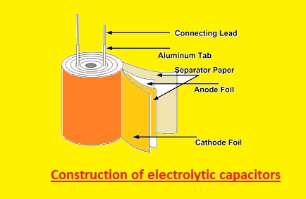
Construction of Electrolytic Capacitors
- An aluminum electrolyte capacitor is made with the use of two aluminum foils and a paper spacer configured on the electrolyte.
- One aluminum foil is covered with an oxide layer, and the foil works as an anode, and the uncoated work as a cathode.
- During normal working conditions, the anode must be more positive than the cathode, so the cathode has a minus sign.
- Anode electrolyte-soaked paper and cathode are stacked.
- The stack is rolled and configured on the cylindrical casing and connected with the use of pins.
- Two geometries are as follows: axial and radial. An axial capacitor comes with a single pin on every side of the cylinder, and a radial structure has both pins on the same side of the cylinder.
Tantalum Electrolytic Capacitor Construction
- This capacitor is made with the use of tantalum metal working anode, which covers the oxide working as a dielectric and a conductive cathode. Tantalum works as thin dielectric layers.
Applications and Uses of Electrolytic Capacitors
- it used in resonant circuits.
- It is used in fading LED circuits.
- Filter circuits, such as high- or low-pass filters, use this module.
- It removes noises from the circuit.
- It is used for smoothing ripples in converters.
Which is better, a ceramic or electrolytic capacitor?
Ceramic Capacitors:
Advantages:
- It has a small size structure, a high capacitance value in a small design, a low ESR value and ESL, and has different voltage ratings and can work for different temperature values.
Disadvantages:
- Its capacitance can be less stable with temperature changes, affected by DC bias voltage, causing microphonic noise and limited capacitance than electrolytic capacitors.
Electrolytic Capacitors:
Advantages:
- It also has a high capacitance value, is best for uses that need larger capacitance, and has features to handle high voltage ratings, the compact size relative to capacitance, and is best to use for energy storage and filtering.
Disadvantages:
- It has sensitive poles, less life than other capacitors, and voltage and temperature limitations as well and also has reliability problems.
The ceramic capacitors are used since they have a small size, less ESR, and high-frequency value and are best for using decoupling, bypassing, and filtering.
Electrolytic capacitors are best for high capacitance value and energy storage and are used in power supply, audio devices, and industrial control systems.
How to Read Capacitance Value?
- First of all, read 2 digits in pico. Farads such as 47 will be read as pF.
- Read 3-digit numbers as base capacitance values in picofarads and multipliers. The first 2 digits will be the base capacitor value in pF. The 3rd digit is a multiplier used on the base number for finding the actual value of the capacitor.
- Use the 3rd digit of zero through five to put the resultant number of Os behind the base value. The 3rd digit, 8, is multiplying the base value with 0.01. The 3rd digit of 9 is multiple base to 0.1. Such as 472 will show a 4700uF capacitor, and 479 will show a 4.7 pF capacitor.
- Some small capacitors have codes like 1n0. Digits are values before and after decimal points, and characters explain dimensions such as 1.0 nF (nano-Farad).

What are the advantages and disadvantages of electrolytic capacitors?
- Here are some advantages and disadvantages of electrolytic capacitors that are explained.
Advantages:
- It has a high value of capacitance.
- It comes in a compact size.
- It is more cost-effective than other high-capacitance capacitor types.
- It has different voltage values.
Disadvantages:
- Its polarity is sensitive, needing accurate polarity connection.
- Its working life is less than other capacitors, and it needed inspection and replacement after some time.
- Its voltage is given, and the temperature is not increase to a certain value.
- It has reliability problems like electrolyte drying, high ESR, or leakage.
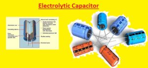
Electrolytic Capacitor’s Inner Structure
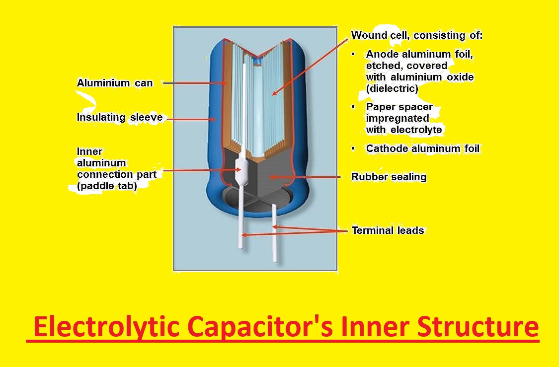
Here you can see the inner structure of the electrolytic capacitor. Mostly electrolytic capacitors are polarized capacitors that are made with two thin layers of metal foil and a paper spacer filled with electrolyte. The dielectric oxide layer works as a dielectric medium and electrical insulation between anode and cathode foil.
The supercapacitors are unique electrolytic capacitors known as double-layer capacitors. its power range is hundreds of Farads to thousands of Farads. The diverse features of oxide structure affect electrolytic capacitors according to features.
Electrolytic capacitors have stable life features, capacitors with low leakage current values, and e-caps have a rated voltage of about 100 volts. All use amorphous oxide anode foils. Capacitors with high voltage, like photoflash capacitors, use crystalline oxide anode foils.
Why Choose Electrolytic Capacitors
The electrolytic capacitor can handle high-frequency circuits that normal ceramic capacitors can do due to high capacitance values. With that, they do a better job than supercapacitors in handling ripple currents. They are made to low volume, which saves a high area of boards with less cost.
How to Read an Electrolytic Capacitor
For SMD electrolytic capacitors, there are two main marking types. The first one defines the value in mF and operating voltage. Such as with the use of this method, the 4.7 μF capacitor having an operating voltage of 25 volts will have a marking of 4.7 25V. For another marking system, the letter is followed with 3 numbers. The first two numbers are picofarads, and the 3rd number is absolute zero. Such a 4.7 μF capacitor with a voltage value of 25 volts number can marking E476. It is equal to 47000000 pF = 47000 nF = 47 μF.
Difference between Ceramic Capacitors & Electrolytic Capacitors
- Electrolytic capacitors come with less stability than ceramic capacitors, and their capacity can be different for high voltage and temperature changes. Ceramic capacitors have high frequency and high voltage conditions with capacity remaining stable.
- The electrolytic capacitors are used for low-frequency decoupling and are part of low-frequency filters. While ceramic capacitors come with features to handle high-frequency noise.
- The structure of an electrolytic capacitor is like a cola can, and the ceramic capacitor is a disc-shaped component and has a size about the size of a coin or even smaller.
- Electrolytic capacitors are polarized, and ceramic capacitors are non-polarized and do not need forward-biased voltage.
Styles of aluminum and tantalum electrolytic capacitors
Aluminum electrolytic capacitors make up the bulk of electrolytic capacitors used for electronics due to the larger diversity of size and less cost of manufacturing. The tantalum electrolytic capacitor is used in the SMD version and has higher specific capacitance than an aluminum electrolytic capacitor and is used in devices having limited space or flat designs like laptops. They are also used in military devices, mostly in axial style, hermetically sealed. Niobium electrolytic chip capacitors are a new development in the market and are used as a replacement for tantalum electrolytic chip capacitors.
How do you identify an electrolytic capacitor?
Read Also:
- On AC Capacitor Wiring Colors – 2024 Complete Guide
- What is the Difference Between: Ceramic vs Electrolytic vs Tantalum Capacitors
- What is a Capacitor Polarity – Construction, Its Types, Function & Applications
- What is the Role of Capacitor in a Ceiling Fan?
- Difference Between Capacitor and Inductor
- Introduction to Capacitor
- What is Synchronous Condenser (Capacitor)
FAQs
Can electrolytic capacitors be used in AC circuits?
- Electrolytic capacitors are used in circuits with positive pins with the positive lead of the supply and then the negative point. Normally used where DC or pulsating DC voltage exists. Some special types of non-polarized electrolytic capacitors are used in AC circuits.
How do we know the correct polarity of an electrolytic capacitor?
- These capacitors look like small tin cans that are polarized. The negative pin of the cap has a minus mark and color strip. The positive pin is a longer size.
Can electrolytic capacitors be used in high-temperature conditions?
- Mostly current capacitors, like aluminum electrolytic or film capacitors, are limited to the work temperature value of
- 125ºC – 150ºC or lower. For getting a high-temperature rating, ceramic and tantalum capacitors are used.
How can I extend the operating life of electrolytic capacitors?
- Capacitor working life increases by a factor of two for each +10°C reduction in temperature. With that, working life reduces through the factor of 2 for a +10°C increase in temperature.
Write the maximum capacitance value of an electrolytic capacitor.
- Electrolytic capacitor capacitance is about 1µF to 47mF. double-layer capacitor, or supercapacitor, has capacitance that can be thousands of farads.
What is the function of an electrolytic capacitor?
- It is used for the reduction of voltage fluctuations in different filtering devices. It is used in output and input smoothing filters when the DC signal is weak with the AC component. They are used for noise filtering or decoupling in power supplies.
What is the difference between a capacitor and an electrolytic capacitor?
- Electrolytic capacitors are best for larger capacitance values for larger ranges that need stable conditions. Ceramic capacitors are good for smaller capacitance values that are used in variable conditions.
What is the formula of a capacitor?
- The capacitance of a capacitor is the ratio of the highest charge Q stored in capacitors to the voltage given about the plates. Capacitance is the highest amount for a charge per voltage stored in the device. C = Q V. C = Q V
Is an electrolytic capacitor AC or DC?
- Electrolytic capacitors are used in circuits that have the end marked positive always at positive potential rather than the negative end. So they are normally used where DC or pulsating DC voltage exists. Special types of non-polarized electrolytic capacitors are used in AC circuits.
What is an example of an electrolytic capacitor?
- A practical example is the use of an electrolytic capacitor as a filter in audio amplifiers, whose main work is to reduce mains hum. The mains hum is 50Hz or 60Hz electrical noise induced from the mains supply that can be audible if amplified.