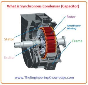
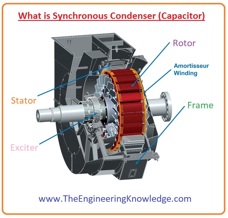
Hello friends, I hope all of you are having fun in your life. In today’s tutorial, we are going to have a look at what a synchronous condenser (capacitor) is and its importance in different electrical machines. In an electrical system, a synchronous condenser is a synchronous motor that gets excitation from a DC source. There is no load connected with its shaft, but it moves without any load. It is also recognized as a synchronous compensator and synchronous capacitor. This motor is not used for mechanical power creation, meaning electrical energy into mechanical transformation, but for the stability of power at the grid station. It stabilizes the P.F. and voltage of the system; for this purpose, its field is regulated by a voltage regulator to get or transmit reactive power according to system requirements. The fitting (installation) of this motor is similar to other electric machines.
The increment of field current of this motor increases the reactive power to the system. Its main benefit is the simplicity with which the quantity of correction can be regulated. Due to some short circuits in machines affecting the stability of a system that is maintained by the K.E. of a rotor of a synchronous motor. These devices are mostly used in such a system where higher-voltage DC conversion occurs and reactive power is maintained by these condensers. In today’s post, we will have a look at its working, circuits, applications, and some other parameters. So let’s get started with what a synchronous condenser (capacitor) is.
Synchronous Capacitor or Synchronous condenser Phasor Diagram
- A synchronous motor brought to run a load can be overexcited to deliver reactive power Q for an electrical system.
- In previous years, these motors were only used for P.F improvements of the system not to run a load
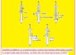
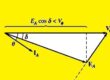
- The phasor diagrams of a synchronous motor working in over-excited conditions without any load are shown below.
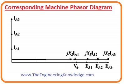
- As there is no load connected with the motor so power (EAsinand Iacosø) drawn from the motor is 0.
- As KVL equation for a synchronous motor is given as.
Vø =EA + jXsIA
- The term jXsIA is pointed towards left in the phasor diagram and armature current Ia by ninety degrees
- if we compare Ia and Vø than we can see that it is like a capacitor.
- An overexcited synchronous motor without any load behaves like a huge capacitor to an electrical network.
Synchronous Capacitor or Condenser V Curve
- The V curve of a synchronous condenser is drawn in a given figure.
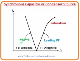
- As the active power provided to the motor is 0, at unity P.F that means the armature current is zero.
- As the IF is augmented over this point, the line current increases in a linear manner until get saturation.
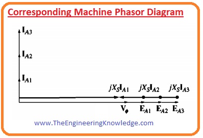
- The given figure shows the result of an increase in IF on the phasor diagram.
- Nowadays, conservative static capacitors are cheaper to purchase and use than a synchronous condenser.
- Nevertheless, some synchronous condensers can still use in older industries.
Synchronous Condenser Applications
These are some important applications of a synchronous condenser.
A synchronous motor in over-excitation states has a leading PF. This feature enhances its use in different industries for power factor improvements.
Induction motor transformers behave like inductive loads and operate at a lagging P.F. When induction motors are connected with light output (load), then the motor consumes the larger value of Q, which decreases the P.F. Due to this, increases in reactive power increase the losses in the system.
So synchronous motors are joined with the induction motors to deliver reactive power to an induction motor. That increases the P.F. of the system and the current drawn from the motor.
The synchronous capacitor has the ability to deliver continuous P.F. improvements with the capability to generate up to one hundred fifty percent extra VARs.
Capacitor Bank Vs Synchronous Capacitor
Through 1950, the working of a synchronous capacitor was very popular in industries.
They remain a replacement of capacitors for P.F. improvements, as due to harmonics in the system, capacitors get overheated and disastrous catastrophes occur.
Synchronous capacitors also maintain voltage. Capacitor banks generate a reactive power in such a way that it is directly proportional to the square of terminal voltages.
So if the voltage of the system connected with the capacitor bank decreases, the capacitor’s reactive power also decreases, and if the system’s voltage increases, then the capacitor’s reactive power also increases, which creates problems.
While in the case of a synchronous capacitor it does not happen; these condensers generate less reactive power in the case of high voltage and high reactive power in the case of less voltage, that remains in the system stable.
A synchronous capacitor is also known as ‘dynamic power factor correction’. These motors are very suitable for such a system where modern controllers are used for regulation of power factors, like PLCs.
A synchronous capacitor is also used to regulate the voltage at distant transmission lines, especially those that are connected with inductive loads.
I have also written some related articles; you can also read them. They are listed here.
- Introduction to Synchronous Motor
- Synchronous Motor Torque-Speed Characteristic Curve
- Synchronous Motor Starting Method
- What is Synchronous Condenser (Capacitor)
- Synchronous Motor Power Correction.
- Types of Synchronous Motor
- Effect of Field Current Changes on a Synchronous Motor.
Friends it is the detailed post on synchronous condenser I have mentioned each and everything related to this post with the detailed. If you have any query about this article can ask in the comments. See you in the next tutorial Synchronous Motor Starting Methods.
.