Hello readers welcome to the new post. Here we will discuss AC Capacitor Wiring Colors – 2023 Complete Guide. In the case of an air conditioning system, the components in the system can be complicated but understanding their functions and wiring is important for accurate maintenance and repair. Among these components, the AC capacitor is important in making sure the smooth working of the AC unit. In this post, we will cover details of AC capacitors’ wiring colors and their importance. So let’s get started with ac capacitor wiring colors.
Understanding AC Capacitors
What is an AC Capacitor?
An AC capacitor is an electrical component tha stores and releases electrical energy in an air conditioning system. It offers an additional jolt of power required to start the compressor and fan motor make sure effective cooling. Capacitors come in differnt types like starting capacitors and run capacitors every does a certain work based on the AC unit’s operation.
Capacitor Types and Their Functions
Start capacitors offer an extra voltage boost for starting the motor, while run capacitors maintain steady electrical flow to make motor operation smooth. These capacitors are important for AC units to work accurately, and knowledge of their wiring is important for accurate installation and function.
Wiring Basics for AC Capacitors
Safety Precautions
Before starting work with AC capacitor wiring, we must focus on safety measures. Always turn off the power supply connected to the AC unit to prevent electrical shocks. Use proper safety gear and follow the best measures to make sure safe working conditions
Wiring Components Overview
AC capacitor wiring does the connection of different components like the compressor, fan motor, and the capacitor itself. Every pin comes with certain wiring colors which is related to its working and the knowledge of these colors is important for accurate installation and troubleshooting.
Common AC Capacitor Wiring Colors
Yellow and Purple Wires: Herm and Fan Terminals
The yellow wire normally connects HERM (hermetically sealed compressor) terminal, while the purple wire attaches to the fan terminal. These wires make sure that power is accurately distributed between the compressor and the fan motor.
Red and Brown Wires: C and F Terminals
The red wire is related to the C (common) terminal, while the brown wire is connected to the F (fan) terminal. The common terminal is important in offering a shared path for the electrical current.
Blue and White Wires: Common and HERM Terminals
The blue wire attaches to the common terminal, making sure of a stable flow of current, while the white wire attaches to the HERM terminal, offering power to the compressor.
Decoding the Wiring Colors
HERM Terminal
The HERM terminal (hermetically sealed compressor) needs a white wire to provdies power to the compressor. It makes sure the proper functioning of the AC unit by offering the necessary electrical energy.
F Terminal
The F terminal attaches to the fan motor with the use of the purple wire. It delivers power to the fan, making it circulate air through the system and contribute to effective cooling.
C Terminal
it is a common terminal, denoted by the red wire, and is the midpoint for electrical current distribution. It makes sure a balanced flow of electricity throughout the AC unit.
Identifying Wires and Terminals
Reading the diagram
To find the accurate wires and terminals, define the wiring diagram provided by the manufacturer. The diagram provides a visual denotation of the components and their configured wiring colors.
Checking Manufacturer’s Information
Manufacturers mostly label the wires and pins for easy verification. Always follow the manufacturer’s guidelines to make sure you’ve configured the right wires to the accurate terminals.
Step-by-Step Wiring Process
Gathering Tools and Materials
Before starting, get the required tools and materials, like wire cutters, electrical tape, wire strippers, and a voltage tester. This makes sure a smooth and effective wiring process.
Turning Off Power
Switch off the power supply to the AC unit to avoid electrical accidents. Use a voltage tester to make sure that there’s no current flowing to the unit before starts working.
Removing the Old Capacitor
Carefully disconnect the wires from the old capacitor, mentioning their positions and colors. Remove the old capacitor from its mounting and dispose of it safely according to local guidelines
Wiring the New Capacitor
Follow the manufacturer’s wiring diagram to configure wires to the corresponding pins on the new capacitor. Use wire connectors and electrical tape to make sure the connections are.
Testing and Final Checks
After wiring the new capacitor, on the power supply, and test the AC unit. Check the unusual noises and make sure that both the compressor and fan motor are running properly. Conduct a final visual inspection to make sure that all connections are secure.
AC capacitor wiring diagram
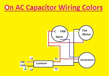
- Here we can see the AC capacitor wiring diagram:
The diagram shows that dual capacitor shows a dual capacitor, is mostly used in AC circuits. The capacitor has 3 pins: C (common), FAN, and HERM. The C terminal is configured to the neutral wire. The FAN terminal is attached with the fan motor’s start winding. The HERM terminal is attached to the compressor’s start winding.
different wires and their corresponding terminals:
Wire Color Terminal Function Black C Common Brown FAN Fan motor start winding Red HERM Compressor start winding It is good to note that the polarity of the wires is important. The FAN and HERM pins must be attached with accurate start windings, or the capacitor will not work correctly
Single-run capacitor wiring
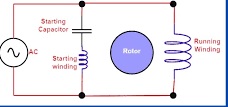
A single-run capacitor is a capacitor type that is used to start a motor and run accurately. It is normally wired in series combination with the main winding of the motor and it helps to offer a smooth flow of the current of the motor. The wiring of the single-run capacitor is simple. The capacitor comes with two leads, that is mentioned C and L. The C pin is connected with a common pin on the motor and L pin is attached with a lead that denoted as the Run
Here we can see a diagram of the wiring for a single-run capacitor:
Where:
- M = Motor
- C = Common terminal
- L = Run lead
It is good to note that the capacitor should be accuralty in size for the motor. The capacitance of the capacitor rating is normally mentioned on the capacitor.
To install a single-run capacitor, just need to disconnect the power to the motor. When power is disconnected we can remove the older capacitor and connect a new one. Make sure to connect new capacitor pins with accurate pins of motors
When the capacitor is connected we can reconnect the power to motor and test it to confirm that it is working accurately.
Here are some safety measures during working with single-run capacitors:
- Always disconnect the power with the motor before working on it.
- Do not touch the capacitor’s pins when the power is attached.
- Make sure to use the accurate size capacitor for the motor.
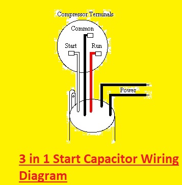
3 in 1 Start Capacitor Wiring Diagram
The 3 in 1 capacitor has 5 wires:
- White: it connects with the starting terminal on the compressor.
- Black: This wire attaches to the common terminal on the compressor.
- Red: it connects to the run terminal on the compressor.
- L1: This wire is configured to the line voltage (hot) wire.
- N: This wire connects to the neutral wire.
To wire the 3 in 1 capacitor, connect the white wire to starting terminal black wire with the common pin, and the red wire to the run terminal. After that connect L1 and N wires to the related pins on the capacitor.
Here are some more tips for wiring a 3-in-1 start capacitor:
- Ensure that the power is turned off before you start wiring.
- Use the accurate color wires for each terminal.
- Tighten the wire connections strongly
- Test the capacitor after you have wired it to ensure that it is working accurately
How Do You Wire a Hard Start Capacitor
Here are the for how to wire a hard start capacitor:
- Turn off the power to the air conditioner.
- Find the capacitor on the air conditioner. It is normally located close to the compressor.
- Find the terminals on the capacitor. There are two main terminals, labeled “Common” and “Start.”
- Attach the black wire from the capacitor to the “Common” pin on the air conditioner.
- Attach the red wire from the capacitor with the “Start” terminal on the air conditioner.
- Turn the power on to the air conditioner.
Here are some more tips for wiring a hard start capacitor:
- Use a multimeter to check that the capacitor is the accurate size and voltage for the air conditioner.
- Ensure that the wire connections are tight.
- Test the air conditioner when you have wired the capacitor to ensure that it is working properly.
What Are the 3 Pins on a Refrigerator Compressor
The 3 pins on a refrigerator compressor are labeled “S”, “C”, and “R”. These letters full form is
- S: Start
- C: Common
- R: Run
The start winding is employed to start the compressor. It is a high-amp winding that is just energized for a short period of time. The common winding is the main winding that offers the power to run the compressor. The run winding is a low-amp winding that is energized regularly
The 3 pins are normally attached to a start capacitor, which helps to start the compressor. The start capacitor offers a temporary boost of voltage to the start winding, which helps to minimize the inertia of the compressor.
If the 3 pins on the refrigerator compressor are not labeled, we can use a multimeter to identify them. Set the multimeter to the ohms value and touch the pins to each of the pins. The start winding will have the low resistance, the common winding will come with the 2nd lowest resistance, and the run winding will have the high resistance.
How Do You Bypass a Compressor Relay on a Refrigerator
Bypass the compressor relay on a refrigerator only as a temporary measurement to test the compressor. Bypass is not a permanent solution.
Here are the points for how to bypass a compressor relay on a refrigerator:
- Unplug the refrigerator from the power outlet.
- Find the compressor relay. It is normally located on the compressor or on the control board.
- Find the 2 terminals of the compressor relay that are attached to the power supply.
- Use a jumper wire to attach the two terminals.
- Plug the refrigerator back into the power outlet.
- The compressor should now turn on.
Note:
- Be certain to use a jumper wire that has a similar rating for the same voltage as the power supply.
- Do not bypass the compressor relay if you are not easily working with electrical components.
If the compressor turns on when you bypass the relay, then the relay is faulty and must be changed. If the compressor does not turn on, then there is another issue with the refrigerator and you have to get the services of a technician.
Here are some main causes for compressor relay might fail:
- Overheating: The relay can be overheating if there is high current passing through it. it can cause if the compressor is overloaded or if there is a short circuit in the wiring this can happen
- Wear and tear: The electrical connections in the relay can wear down with time. This can cause the relay to be damaged to close accurately, which will avoid the compressor from turning on.
- Debris: Debris can cause the relay contacts on and avoids them from making good contact. It can also cause the relay to fail.
Do You Know About AC Capacitor Terminals?
Yes, I do. AC capacitor pins are the electrical connections that help the capacitor to be wired into an AC circuit. There are normally three terminals on an AC capacitor:
- Common (COM): This pin is connected to the common or neutral wire in the circuit.
- Hermetic (HERM): This pin is attached to the hermetic compressor in the circuit.
- Fan (FAN): it is connected to the condenser fan motor in the circuit.
The specific terminals that are employed on an AC capacitor will changes based on the capacitor type and the application. For instance, a dual-run capacitor will come with all three terminals, while a start capacitor will have the HERM and COM terminals.
It is good to attach the AC capacitor terminals accurately to minimize damage to the capacitor or the other elements in the circuit. The pins are normally labeled with the corresponding letters, but it is a good idea to double-check the wiring diagram before making any connections.
Here are some more things to note about AC capacitor terminals:
- The terminals must be clean and free of corrosion before making any configurations.
- The wires must be accurately sized and insulated to match the voltage and current rating of the capacitor.
- The connections must be secure and tight to avoid arcing or overheating.
Ac Capacitor Wiring Colors
The most common color codes for AC capacitor terminals are:
- C (or Common): Black
- FAN (or Fan): Brown
- HERM (or Herm): Red
- COM : Yellow
These colors are employed to indicate the function of the terminal to which the wire is attached. For instance, the black wire must be configured with the C terminal, which is the common terminal. The brown wire must be connected to the FAN terminal, which is the pin for the fan motor. The red wire can be attached to the HERM terminal, which is the pin for the compressor.
It is good to note that these are just the most common color codes. Certain wire color codes can changes based on the manufacturer or region. If you are not sure of the color codes for your AC capacitor, it is good to follow the manufacturer’s documentation.
most common AC capacitor wiring colors:
Terminal | Color | Function |
---|---|---|
C (or Common) | Black | Common terminal |
FAN (or Fan) | Brown | Terminal for the fan motor |
HERM (or Herm) | Red | Terminal for the compressor |
COM | Yellow | Common terminal |
Pointers About Standard & Non-Standard Colors Guide
1. Color Basics:
- Start with knowledge of the color wheel, primary, secondary, and tertiary colors.
- Define the concepts of colors, saturation, and brightness (value).
2. Color Psychology:
- Define the emotional and psychological effects of different colors. For instance, the blue color represents calmness and trust, while red defines energy and passion.
- Highlight cultural and regional changes in color symbolism.
3. Color Harmony:
- Find different color schemes like complementary, triadic, analogous, and monochromatic.
- Explain the use of color harmony to make visually pleasing designs and combinations.
4. Color Mixing:
- Detail the process of mixing colors to get the required shades.
- Include tips for getting consistent color mixing in many mediums like digital design, paint, and textiles.
5. Standard Color Systems:
- Use widely-used color systems like CMYK (for printing), RGB (for digital displays), and Pantone (for standardized color matching).
- Define the purpose and usage of each system.
6. Non-Standard Colors:
- Cover unconventional or non-standard colors like pastels, metallics, neons, and fluorescents.
- Gives details of when and how to effectively use these colors.
7. Color Accessibility:
- Check the importance of color contrast for readability, especially in web design and accessibility standards.
- Offer details for making designs that are added to individuals with color vision deficiencies.
8. Color in Design Contexts:
- Define color usage in various design disciplines, like graphic design, fashion, interior design, and branding.
- Provides real-world examples of successful color applications in each context.
9. Trends and Innovations:
- Must be updated with current color trends and emerging innovations in color technology.
- Gives details on how these trends are affecting design and aesthetics.
10. Practical Exercises:
- Add hands-on exercises and projects to help readers experiment with color combinations and get practical experience.
11. Resources and Tools:
- Have a list of color-related resources, like online color converters, color palette generators, and tools for color blindness simulation.
12. Case Studies:
- Define case studies of famous designs, artworks, or products that effectively use color to deliver messages or evoke emotions.
note that, a successful guide on standard and non-standard colors must be visually engaging, well-organized, and user-friendly. It must empower readers to make informed color options and inspires creative exploration.
Faqs
- What color is the common wire on a capacitor?
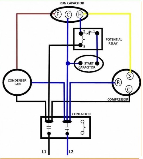
- The common wire on a capacitor is normally colored black or marked with a “C” for identification.
- How is a capacitor wired?
- A capacitor is wired by connection with one terminal to a power supply (positive) and the other pin with a load or ground (negative).
- What is the capacitor connection in AC?
- In AC (alternating current) circuits, capacitors can be configured in series or parallel combinations to modify the circuit’s operation. Series connection comes with connecting the positive terminal of 1 capacitor with the negative terminal of another, while parallel connection comes with connecting positive terminals together and negative terminals together.
- Does it matter which wire goes where on a capacitor?
- Yes, it matters. Connecting a capacitor in reverse polarity can damage the capacitor and affect the circuit’s working
- Can a capacitor be wired wrong?
- Yes, a capacitor can be wired incorrectly if the positive and negative terminals are reversed state. it can cause malfunction or failure.
- What are the positive and negative wires on a capacitor?
- A capacitor has2 pins: the longer one is normally the positive terminal, while the shorter one is the negative pin.
- Do AC capacitors have positive and negative?
- Yes, AC capacitors also have positive and negative terminals. Correct polarity is important for accurate functioning.
- How do I identify the positive side of a capacitor?
- The positive pin of a capacitor is indicated by a longer terminal lead, a “+” symbol, or a marking near the positive terminal.
- Which is the positive or negative wire?
- The wire configured to the longer terminal or marked with a positive sign (“+”) is the positive wire. The short pin related to the negative wire.