 Hello, friends, I hope all of you are enjoying your life. In today’s tutorial, we will have a look at Introduction to Proteus. I am going to start a new tutorial series on proteus software. This is the first tutorial of this proteus series in which I will give you a detailed introduction to proteus and its different elementIntroduction to Proteus. It is a circuit designing software invented by Labcenter Electronics. It is used to design different circuits on PCB (printed circuit board) and simulation of different circuits. The use of proteus for any electronic circuit project makes that project cost-effective and less errored due to schematic construction on the proteus.
In 1988 the first version of Proteus known as PCB-B was created by John Jameson who was chairman of the company. In today’s post, we will have a detailed look at its uses, and structure, and will learn how to make different circuits in Proteus. So let’s get started with Introduction to Proteus.
Introduction to Proteus
- Proteus is used to simulate, design, and drawing of electronic circuits. It was invented by Labcenter Electronics.
- By using proteus you can make two-dimensional circuit designs as well.
- With the use of this engineering software, you can construct and simulate different electrical and electronic circuits on your personal computers or laptops.
- There are numerous benefits to simulating circuits on proteus before making them practically.
- Designing of circuits on the proteus takes less time than practical construction of the circuit.
- The possibility of error is less in software simulation such as loose connection that takes a lot of time to find out connection problems in a practical circuit.
- Circuit simulations provide the main feature that some components of circuits are not practical then you can construct your circuit on proteus.
- There is zero possibility of burning and damaging of any electronic component in Proteus.
- Electronic tools that are very expensive can easily get in proteus such as an oscilloscope.
- Using proteus you can find different parents of circuits such as current, the voltage value of any component, and resistance at any instant which is very difficult in a practical circuit.
Features of Proteus
- There are 2 main parts of proteus first is used to design and draw different circuits and the second is for designing of PCB layout.
- First is ISIS used to design and simulate circuits. And second is ARES used for designing a printed circuit board.
- It also provides features related to the three-dimensional view of design in PCB.
Proteus Layout
- Friends, now we discuss the layout of proteus and will discuss sections and their functionality in proteus.
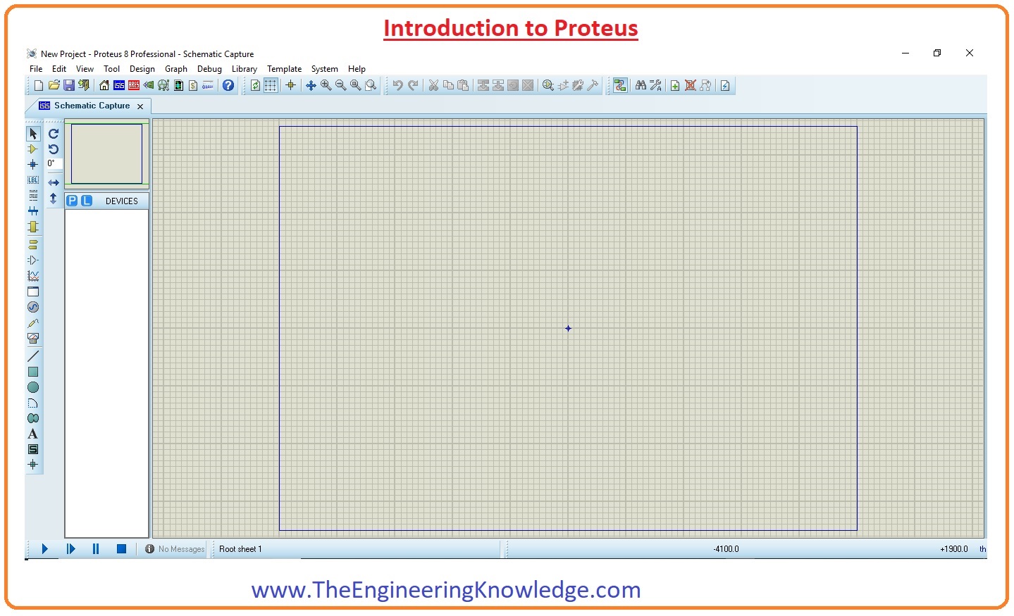
- When you will click on the Icone of installed Proteus in your computer then you will see this window from a new file option.
- In the above figure, you can see the proteus window and this window has many sections that are explained in the below figure.
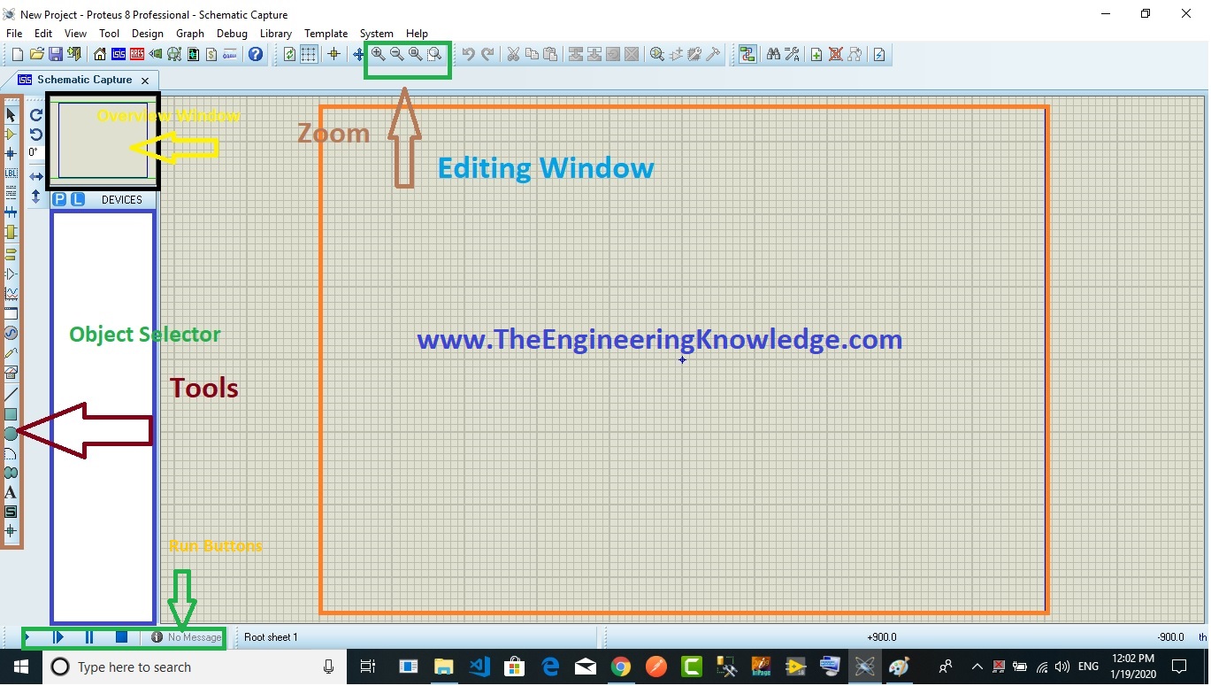
Editing Window
- In the above figure, you can see that the dotted portion is called an editing window. This is a drawing portion of proteus where you simulate your engineering circuits and projects.
Overview Window
- In the overview window, you see the complete view of your complete design.
Object Selector
- This section has 2 buttons P and E. P is used to select different components and shown in this box. The E button is for editing something for example you want to vary any value of components then you can use this edit button.
Zoom Option
- By using this option you can easily zoom in and zoom out your layout and can observe the complete simulation very clearly.
Tool Option
- By using this option you can select different devices like voltmeter, ammeter, oscilloscope, etc.
Run Buttons
- At the left bottom, there are 4 buttons Run, stop, pause, and stop. These buttons are like the remort control and are on and off your circuit.
How to Make Circuit in Proteus
- Lets friends now discuss how you can make any electric circuit in proteus.
- We will perform some steps to make a circuit.
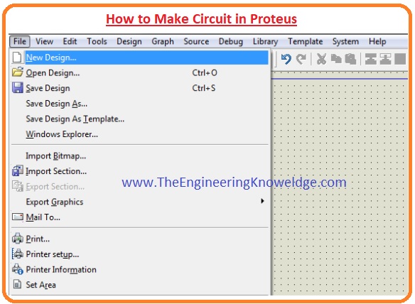
Step 1:
- First of all click on Proteus Icone in your computer and click on a new file option as shown in the below figure.
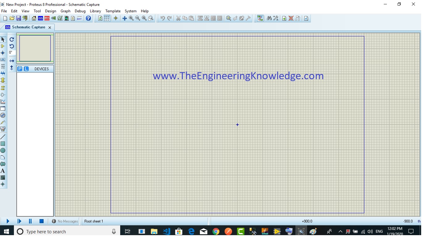
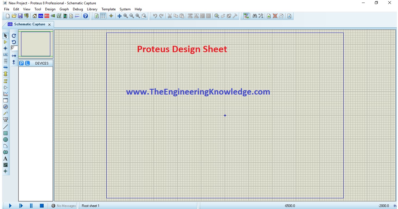
Step 2:
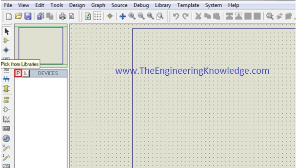
- After that, you will see the drawing sheet as shown in the below figure. Save it according to your project.
Step 3:
- After a move to the component option as shown in the below figure and select the elements for your projects.

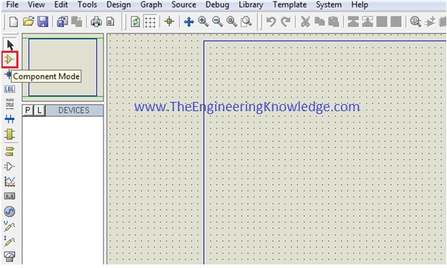
Step 4:
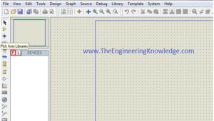
- After clicking on components mode you will see two buttons P and L. If you move to P button you will see Pic from Libraries.
- It is used to select different components for circuit construction.
Step 5:
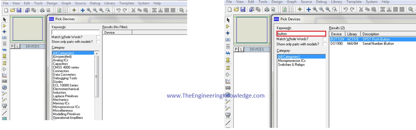
- When you click on the P button you will see box shown in the below figure. Type your component for a circuit.
- As I type the button and you can see a button in the right figure that different buttons are shown you can select according to your use.

Step 6:
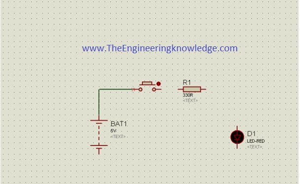
- When you will select components for your project you will see them in a box shown in the below figure.
- I have also selected some components for designing of a simple circuit.
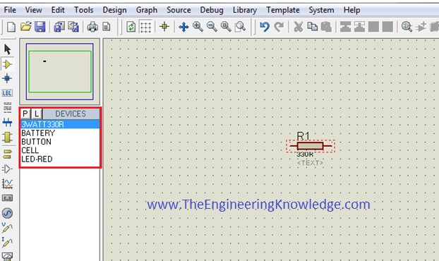
- After the selection of components make the circuit layout of your project and connect all these components with the wires.
- For connection of one component to another click the left of the first terminal of the component and drag it to other components.
- If you want to remove any component or remove its connection just double-click on the respective component of the wire.
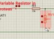
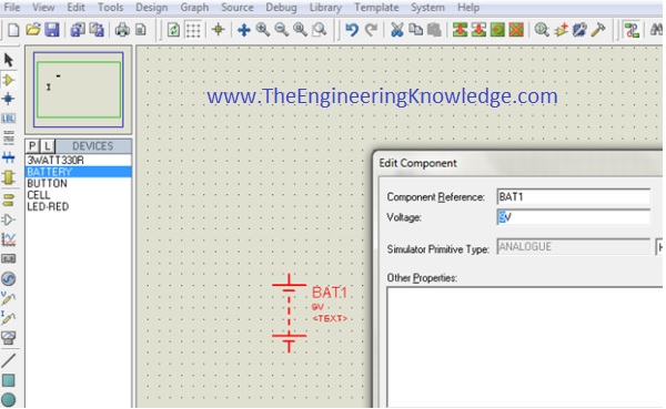
- If you want to change the values of any component such as resistance, or capacitor, then click right on that component and select the desired value and click OK button.
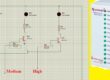
- As in the below figure, I vary the value of battery voltages.
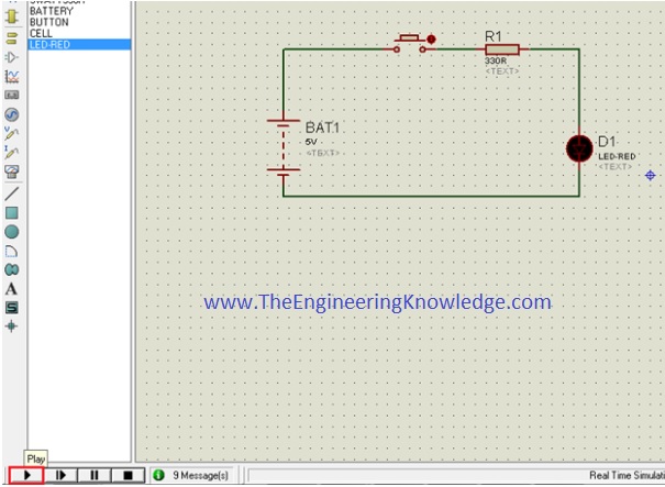
Step 7:
- When you connect all components in the circuit like run button in the left bottom see the practical working of your circuit.
Step 8:
- When you will observe the simulation of your circuit than click on the stop button on the left bottom to stop the working of the circuit.
Advanced Features and Capabilities of Proteus
- Footprint libraries
- Manual routing
- Templates and technology data
- Power planes
- Verification
- 3D visualization
- Stitching and shielding
I also have uploaded a video for Proteus simulation that will your practical understanding of Proteus.
Read also:
- Dual Power Supply Circuit-Proteus Simulation
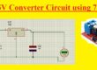
- 12V to 5V Converter Circuit Proteus Simulation
- Virtual Terminal in Proteus Simulation
- Zener Diode as Voltage Regulator Proteus Simulation
- Sound Generator Project Simulation
- 555 Timer LED Brightness Controller Simulation
Faqs
- Proteus is simulation software that can simulate analog circuits, digital circuits, microcomputer circuits, and embedded system
- Proteus software is used for designing and integrating circuits. After designing a circuit with different components like switches, controllers, and LED, it also has simulation and testing design circuits. After testing we make these circuits practically.
- The main advantage of Proteus software is the simple integration between PCB design and simulation. Contrary to other design tools that needed separate software for simulation, proteus helps to easily switch between design and simulation modes.
- Proteus design is used in High Schools, Colleges and Universities all over the world, teaching electronics, embedded design, and PCB layouts made by students in every year. Circuit simulation give students fast and practical learning tool
How to design PCB using Proteus?
- Installing Proteus 8.
- : Getting Started
- : Put Components.
- Making the Schematic. …
- Preparation for PCB Design..
- PCB Design. .
- 3D View.
- Printing Out PCB for Etching
- Proteus PCB software combines Schematic Capture and PCB Layout modules for providing easy and high power and easy-to-use tools for professional PCB design.
Which software is used for PCB design?
| Software | Benefits | Learning Curve |
| Altium | Advanced design environment | Steep |
| Cadence Allegro | Complete lifecycle design management | Very steep |
| Mentor Xpedition | Ease of adoption, analysis integration | Moderate |
| CadSoft Eagle | Affordable, maker community | Shallow |
- OrCAD PCB Designer comes with features such as Manufacturing, Routing, Design Export and Data Import/Export Proteus PCB design used for features like 2D Drawing, , 3D Modeling Collaboration Tools and 3D Visualization.
- The minimum memory need for Protus is 3 GB of RAM installed on computer. With that game developers uses about 4 GB of RAM in your system. An Intel Pentium 4 1.80GHz CPU can used for operating Proteus.
So friends that is the detailed tutorial on introduction to Proteus. I hope you understand this basic tutorial on Proteus very well. If you have any queries ask in the comments. Soon I will upload the second tutorial of this Proteus series. Have a good day.