 Hello, readers welcome to the new post. Today we will discuss Water Level Indicator Circuit. You have seen that at your roof tank that when it is filled with water some water gets wasted due to overflow when the tank is full of water. So there must be some circuit needed that helps us to reduce this water overflow and indicates to us that the tank has full and we should of the motor that fills the tank. To make this project there is a need for a PCB board and experts to make proper configurations of this project. I am getting the services of PCBWAY which is an electronic-based PCB service-providing company in china. Since last decade it is working as the top PCB supplier and PCB prototyping service provider with low-volume manufacturing. Its turnaround time is about twenty-four hours when you send Gerber files that are also approved by their engineers. On the basis of your budget time for a product can be adjusted normally PCBWAY lead time is about 48 hours to 72 hours.
As they are providing high-speed service but they maintain high-quality products. Their customers are also satisfied with their features and services. With quality, their prices are also affordable in five dollars you can get ten PCBs.
The lead time schedule for Standard PCB order are mentioned bellow
As PCBWAY has reduced the delivery time but makes sure quality is created by chemical procedures for pads and vias metallization and avoids conductive adhesive techniques to reduce the prices and every product faces copper plating for seventy minutes Aoi and probe testing

With the decrement in delivery time PCBWAY, they not only decrease the cost for small batch PCB but also manage the prices for DHL parcels that have less than one KG weight. So all in all PCBWAY is the best in all services and features that you needed.
In this tutorial, we will learn the circuit that will help us to control the water flow according to our requirements.
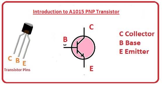
Introduction to A1015 Transistor
- The A1015 is PNP transistor that comes with features of low volts and low power structure so preferred for different applications.
- The current gain value for this component is 70 to 400 preferred to use for amplifier circuits and its maximum gain is moderate
- This module uses about 150mA current at the collector through current values peak load current can be measured for transistors since all applications of transistors are based on current parameters.
- The power used for this transistor is 400Ma and net power dissipation for this module can be defined and it has TO-92 packaging.
- It has a transition frequency value of 80MHz that helps to use for switching circuits.
- The junction temperature for this device is about 150 centigrade

A1015 Transistor Features
- Its main features are discussed here
- Its noise figure is six dB
- The transition frequency for this transistor is 80MHz
- Power dissipation is four hundred mA
- The junction temperature is 150C
- The emitter to base voltage is minus five volts
- VCE is minus fifty
- VCB is minus fifty volts
- Collector current is minus one fifty milliamperes
- It is a general purpose Bipolar transistor.
A1015 Transistor Maximum Ratings
| Parameters | Values | Units |
| Collector-base voltage | -50 | V |
| Collector-emitter voltage | -50 | V |
| Emitter-base voltage | -5 | V |
| IC | -150 | mA |
| Base Current | -50 | mA |
| Collector power dissipation | 400 | MW |
| Junction temperature | 125 | C |
| Storage temperature range | -55 to 125 | C |
Water Level Indicator Circuit
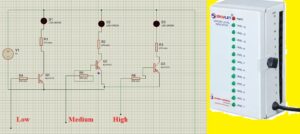
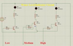
- This water level indicator is using three PNP transistors as switch configurations. Every transistor on the LED is configured to that transistor. LED blinks when a related transistor gets to its base point through water level variation. This circuit is very easy to design and can be constructed at fewer prices

Project Component
- The components used in this circuit are listed here
- LED
- Resistances
- Transistor
- Battery
- PCB from PCBWAY
Water Level Indicator Working

- In this circuit, we will control the 3 levels of the water tank which are low medium, and high.
- In the first case, there is no water in the tank all LEDs will be off which means the tank is empty.
- When water is added to the tank with the water level increases it reaches to low-level transistor Q1 will operate and the LED blink
- When water continues to increase and reaches to mid-level transistor Q2 operated and the current moves to LED 2 that starts to blink
- With that when the tank is filled with water transistor Q3 operated and LED connected to it will blink that is also configured to the buzzer that produces the sound and will indicate to completion of the tank with water so we need to off the motor
- The operation of this circuit is based on the transistor as switch configuration. The base of every transistor is linked with the copper wire that operates as a probe. With the increment of water level signal is given to the transistor through the battery that is nine volts dc. As a result, the transistor operates and the respective LED also gets on to show the water level indication.
Applications
- This circuit is commonly used in industries to control the flow of different liquids in machines
- It used at homes and buildings to control the water flow
- It used in irrigation to control the water flow, fuel tank level gauging, and pump
That is all about the Water Level Indicator Circuit all details has completed about this project if you have any questions ask here. Thanks for reading and for any products you must visit the PCBWAY services


