 Hello, readers welcome to the new post. In this post, we will learn 555 Timer LED Brightness Controller Simulation. LED is type of diode that stands for light-emitting diode. Its configuration is such that when the current passes through this device eliminates the light. The emitted light intensity depends on the current passing through it. The larger the current larger intense light will be eliminated.
Here we make such projects in which we control its intensity of light or brightness through use of an integrated circuit that is 555 timer. This IC is employed in different electronic-related projects to offers the required oscillation and delay in the project. There are three modes of operation it has. Here further I want to mention that the board we are going to use in this project is created from the most famous and high quality PCB supplier PCBWAY. That comes with the different services and projects based on PCB and its related products. All dimensions and parameters of our projects are fully added in our boards and their technical team made a full connection to us to the completion of our products means they offer high quality and favorable services to their clients to fulfill their requirements. They also support us fully to complete our board. So let get started.

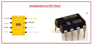
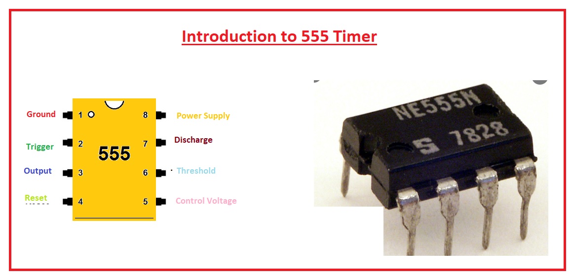
Introduction to 555 Timer
- The 555 timer is integrated circuitry used in such applications where usage of pulse, delay of time, and oscillation is needed.
- There are 2 modules of 556 in single packaging and four 558 modules in a single casing.
- The first time it was used in 1972. There are many manufacturers are creating this device.
- There are normally twenty-five transistors fifteen resistances and two diodes positioned a single board.
- This board comes up with eight pinouts that are dual inline packaging.
- Some modules of these categories like 556 come with fourteen pinouts and 558 has sixteen pinouts.
- Its temperature range where it works is between zero to seventy centigrade.
- The voltage range for which it operates is 4.5 volts to fifteen volts dc.
- There are flip flops, voltage dividers and comparators configured at the board of this device.
- normally it employed to offer the time delay where it used.
- It operation modes are monostable, bistable.
- It comprises of 3 resistances of five kilo-ohms in series combination to voltage dividers modules known as 555 timers.
- It provides the larger value current at the output terminal so used to operates TTL.
Applications of 555 Timer
- The main applications of 555 timers are explained here with detail.
- It employed an analog frequency meter.
- Used in cable testing devices.
- used as a frequency divider.
- DC to DC conversion module has this IC.
- It is used to measure temperature.
- Used in the traffic signal.
555 Timer LED Brightness Controller Simulation
- Have you ever observed that while taking pictures through a camera, flickering occurs when you vary the light brightness of the LED it is caused due to the standard LED?
- Here we making a circuit designed at the high-level PCB boards that is designed from the PCBWAY.
- In this project, there is the usage of potentiometers and transistors that are regulating the brightness of the Light-emitting diode.
- The main components used in projects are listed here.
- PCB from PCBWAY.
- Transistors
- Resistances
- Capacitors
- Potentiometer
- In this circuitry, the 555 timers are operating in the Astable mode. There is the connection of one-kilo resistance and potentiometers and capacitor to the pinouts of two six and seven of 555 timers.
- There is an output pulse is taken out from the pinout no three of the timers. This output is given to the light-emitting diode with the use of NPN transistors and resistances of one kilo-ohm.
555 Timer Features
- Its working voltage range is +5 Volts to +18 Volts supply voltage.
- The load current value is 20 milliamperes. The external component is chosen properly so timing intervals can made in different minutes with a frequency of more than a hundred kilohertz.
- The output pin of the 555 timer operates transistor-transistor logic due to high current output.
- It comes with a stable temperature of 50 parts per million single degrees centigrade changes in temperature that is equivalent to 0.005 %/ °C.
- it has an adjustable duty cycle. The high power dissipation per package is 600mW and the rigger pulse and reset input comes with logic support.
555 Timer Working Mode
Astable Mode
- In this mode, there is no stable output value. So output will change from high to low. This feature of unstable output is employed for clock signals for different circuits
Monostable Mode
- It comes with one stable and one unstable mode. The stable conditions are selected as high or low. If the stable output is at high 1 and the output of the timer is high 1.
- The use of interrupt timer output becomes zero. As the low state is unstable it moves to high 1 after interrupt uses.
Bi-stable Mode
- For bistable mode both output conditions are stable. Each interrupt output varies from low to high and high to low. Such as if there is high output it becomes low when it gets interrupted and low remains until the next interrupt varies the status.
Read also
- Latch Circuit using 555 Timer
- Introduction to 555 Timer, Working, Circuit, Pinout & Applications
- How to Stop Dimmable LED Flash and Flickering
- Introduction to CD 4017 IC
- Fading LED Light Circuit-Proteus
That is all about the 555 Timer LED Brightness Controller Simulation. I have explained every parameter related to this project with detail. If something has to get more please mention it in the comment box. I will resolve your problem thanks for reading have a nice day. See you in the next post.