 Hello friends, I hope you are doing great. In today’s tutorial, we will have a look at Diode Limiters Circuits. In some circuits, the ac signal is used at some certain level to achieve that level AC input signal is limited at certain values. A circuit used to limit a signal at a specified value is known as a diode limiter. In these circuits, a diode is connected in parallel combination with the input signal.
In some circuits, only one half of the wave is to be limited so one diode is connected with the input AC source. But if a complete signal or both half of the sine waveform is to be limited then two diodes are used. In today’s post, we will have a detailed look at its working, circuit arrangements, applications, and some related parameters. So let’s get started with the Diode Limiters Circuits.
Diode Limiters Circuits
- Diode limiters are also known as clipper circuits that used to clip some portion of the signal.
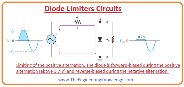
- In the below figure, you can see a diode is connected in an input ac signal as the positive portion of input signal comes across the diode it becomes in forward biased condition.
- In the above circuit, you can see that this positive signal is limited to +0.7 volts as it set to that value.
- When the input signal goes towards a negative signal diode is now in reverse biased condition and operates as an open circuit.
- The output voltage of this circuitry can be calculated by using the voltage divider rule.
Vout = (RL/R1 + RL) Vin
- If the value of resistor R2 is less than the RL then the output voltage will be equal to an output voltage.
Vout =Vin
- If we vary the direction of the diode as shown in the figure the negative portion of input signal will be limit.
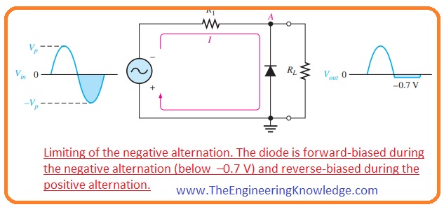
- In this state, a diode is forward biased during a negative cycle of a signal and -0.7 volts will be drop across the diode.
- When the voltage value is larger than the -o.7 volts and a diode is not in a forward-biased condition voltage value across the load resistor is equal to the input supply.
Biased Limiters
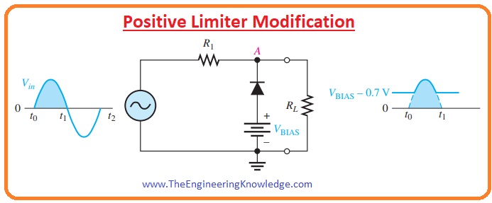
- In some conditions, we required voltage above the 0.7 volts or -0.7 volts in these cases biased limiter circuits are used.
- The limited voltage can be adjusted by using a bias voltage. This VBIAS is connected in series with the diode as shown in below figure.

- The voltage across should be equal to the VBIAS + 0.7 before it operates in forward bias.
- The VBIAS are voltage that will fulfill our requirement after adding in 0.7 volts.
- After conducting diode all voltage at the input of the diode will limit to the VBIAS + 0.7 and the value of voltage above this voltage will be clipped off or limited.
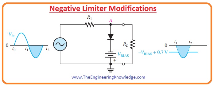
- If we require to limit the negative portion of the input signal then the connection arrangements of diode and battery should be according to given below figure.
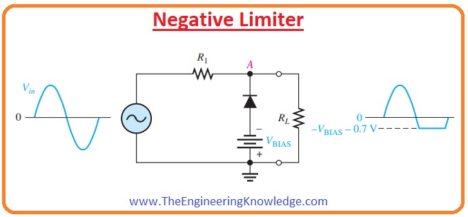
- In this case, the voltage at point ‘A’ will be should go below to the -VBIAS – 0.7 to make diode forward biased and limit the signal.
- If you change the direction of the diode than a positive limiter will provide an improvement in its function and will limit the input signal to level as shown in the below figure.
- Like the positive limiter negative limiter can also be modified and limit the input voltage below -VBIAS + 0.7 V shown in the below figure.
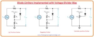
Voltage-Divider Bias
- Above we discuss the voltage source as biased voltage now we replace it with the voltage divider circuit of resistances and provide voltage it through dc supply.
- The value of the voltage divider formula decides this resistance’s biased voltage.
VBIAS = (R3/R2 + R3) VSUPPLY
- In the below figure, there are positive limiters, negative limiters, and variable positive limiter circuits are shown.
 Diode Limiter Circuit Applications

- These are some applications of diode limiter circuits,
- These circuits are used in the production of waveforms and the design of their physical arrangments.
- It provides protection to any circuitry from spikes.
- It also restores the amplitude of any waveform.
- It is used to limit the value of voltage.
- It is also used in TVs.
- The transmitters of frequency modulation also consist of diode limiters or clipper circuits.
voltage limiter diode
- The diode limiter is known as a clipper since it is used to limit input voltage. The diode limiter circuit comes with a resistor and diode. Based on teh circuit and biasing circuit can clip or reduce all or some part input signal. It is used to limit the output voltage to a certain value
Voltage limiter circuit
- The limiter circuit can be used to limit the output voltage to increase from a certain defined value. There is higher or low clipper circuits that do not help the certain value of the signal to increase
voltage limiter circuit using a diode
- There is another name for the diode limiter is clipper due to its use in input voltage limiter. The diode limiter circuit has a diode and resistor.
Read also:
- What is a Rectifier Diode? Symbol & Uses, Applications
- Introduction to FR102 Diode Pinout, Datasheet, Applications, Uses Features
- Forward biased p-n junction diode
- Types of Diode and Applications
- Three Phase Half Wave Rectifier Circuit
- Introduction to Rectifier, Working, Types, Circuit,Features& Applications
Faqs
What is the use of limiter circuit?
- These circuits help signals to be less than a certain input value to move without any effects from the attenuation of a high value of high strength signal that is larger than this value. The limiting process belongs to dynamic range compression.
What are diode limiters and clampers?
- Diode limiter circuits are used to clip off part of signal voltage below or above a certain value and this circuit is called a limiter or clipper. Clamper is used to restore or add dc value to the electrical signal
What is a type of limiter circuit?
- There are main five types of limiter circuits that are series-positive, parallel-positive, parallel-negative, series-negative, and dual-diode limiters.
What are the applications of limiters and clippers?
- Limiter circuits are used to clip off part of the signal voltage and a clipper is used to restore the DC level of the signal
What is the difference between a limiter and a clipper?
- The Clipper circuit does the clipp-off signal to make it to the required value and the limiter makes the amplitude of the single to a threshold value
Why are clippers also known as limiters?
- Clippers are called limiters since they clip off or input signals, without distortion to the other part of the signal
What are the different types of voltage limiters?
- Types of limiters are
- Soft Limiter, Hard Limiter Single Limiter Double Limiter
How do limiters prevent clipping?
- The limiter catches the loudest peak of the audio source and applies brick wall compression that avoids exceeding the clipping point of 0 dBFS.
- Limiters are used for increasing perceived loudness with the increasing quietest part of the audio signal and avoiding peaks from clipping.
So friends that is a detailed post about diode limiters I have mentioned each and every parameter related to diode limiters. If you have any further questions ask in the comments. Thanks for reading. See you in the next interesting tutorial. Have a good day.