 Hello friends, I hope all of you are having fun in your life. In today’s tutorial, we are gonna have a look at How to Find Induced Voltage in AC Machines. AC machines are such electric operating devices that use alternating current for their operation. These machines can be motors and generators. Motor transforms electrical energy into mechanical energy while the generator converts mechanical energy into electrical energy. The operation of these machines either generator or motor depends on the rotating magnetic field that produced at the stator of these machines.
There are two main types of these machines according to input supply connected, The first one is single phase ac machines and second is three-phase ac machines. These are further divided into single-phase motor, three-phase motor, ac generator, synchronous motors, synchronous generator, induction machines are also known as asynchronous machines because their rotation speed is less than the synchronous speed it is the speed of rotation of field at the stator of these machines. In today’s post how rotating field helps to generate a voltage in these machines, and how to relate to one another. So let’s get started with How to Find Induced Voltage In AC Machines.
How to Find Induced Voltage In AC Machines
- As we have studied that the 3-phase currents can generate the rotating magnetic field, this field can generate three-phase voltages in the stating part of the machine.
- The expression will describe the production of three-phase voltage in the stator we will find.
- To make easy calculations first we find the values at a single wound coil and then will finds parameters for three-phase stators.
Induced Voltage in a Coil on a Two-Pole Stator
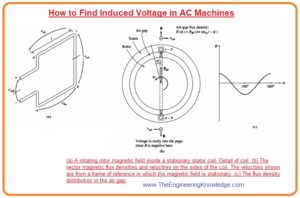
- You can see in the given figure that there is a rotor that is rotating with a sine waveform field that spread on its static part (stator) windings.
- You can see that it is the reversed phenomena that we discussed in the article of a simple loop in the field. In which loop was in rotating state and the field was static.
- Let’s suppose that the flux changes among the stator and the rotor in sine waveform with the mechanical angle and field direction is towards outwards.
- This kind of flux spreading is liked by machine designers.
- If is the angle calculated from the maximum value of flux, then the values of flux at a point near the rotor will be given as.
B = BM cos
- You can see that at some points near the air-gap the direction of the flux is to the rotor at these points the sign of above-given expression is negative.
- As the rotor is in motion state in the stator with the angular frequency (wm) the value of flux at any angle about the stator is given as.
B =BM cos (wt -α )
- As the equation of emf induced in the single loop is.
e= (v x B) ·l
- In this equation, V is the velocity of the loop with respect to the field.
- B is the flux density.
- L is the length of the conductor in the wire.
- As this equation is for the single loop which is moving in the field but in this case the loop is static, but the field is moving sinusdually, so we cannot apply this equation without some modification.
- To apply this equation, we should have such a situation where the field is static.
- Let’s suppose someone of us sit on the field to consider the field in a static condition, then the loop will move in the field, so we can apply this equation.
- The figure which is denoted as B expresses the field and velocities of the static field and the moving coil.
- The net voltage produced in the loop will be equal to the sum of voltage produced in its 4 sides.
- The voltage on each side of the loop is calculated here.
Side ab:
- For the side ab of the loop the angle (α) is 180 degree and suppose that the direction of the field is outward from the rotor, the angle amid the V and field b in this side will be 90 degree whereas the term (V x B) is in the direction of the length (l). so, the equation is.
eab= (V x B). l
=VBl direction toward out of the page.
= – V[BM cos (wmt – 180°)] . l
= – vBMl cos (wmt – 180°)
- In this expression, the minus sign tells that the voltage is produced with a polarity reverse to the presumed polarity.
Side bc:
- The voltage induced on the side BC is 0, because the term (V x B) is at 900 to the length. so the emf induced will be.
ecb = (v x B) .I = 0
Side cd:
- For the side cd the angle α is zero. Let’s suppose that the direction of the field b is outward from the rotor, the angle amid V and b in the side cd is 90 degrees whereas the term (V x B) is in the direction of the length l. se the emf induced is.
ecd = (v x B).I
= vBI direction out of the page.
= v(BM cos wmt) . l
= vBml cos wmt
Side da:
- The voltage induced on this side will be zero as the term (V x B) is at 90 degrees to the length l.
ead = (v x B). I = 0
- So, the total voltage induced on the coil will be the sum of the voltage at four sides.
eind = eba + edc
= – vBMl cos(wmt – 180°) + vBMl cos wmt
- As we already know that the.
Since cos (∅) = – cos (ø – 180°),
eind = vBMlcoswmt +VBmlcoswmt
=2vBMI cos wmt
- The speed of the end conductor is v = rwm so the above equation can be written as.
eind = 2(rwm )BMI coswmt
= 2rlBmwm coswmt
- The flux moving through the loop can be express as.
2rlBM
- For the 2-pole stator Wm= We=w, voltage produced can be written as.
eind = w cos wt —-(c)
- The equation c can explain the voltage produced in the single turn of the loop.
- If the windings in the stator has (Nc) no of turns, then the net voltage produced in the coil will be.
eind = Ncøwcos wt
- Note that the voltage induced in the stating part of the AC machine is like a sine waveform which rely on the flux on the machine, the angular frequency (w) of the rotor and constant which is related to the construction of the machine.
Induced Voltage in a Three-Phase Set of Coils
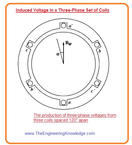
- Now if we put 3 phase windings around the field of the rotor everyone has (Nc) no turns. This assembly is shown in given diagram. The voltage produced in every winding will have similar magnitude but these will be out of phase one twenty (1200).
- The induced voltage in every winding is given here.
Eaa’(t) =Ncøwsinwt V
Ebb’(t) =Ncøwsin(wt-1200) V
Ecc’(t) =Ncøwsin(wt-2400) V
- So, the 3 phase currents can produce the field in the stator, and the resultant field can produce 4 phase voltages in the stator of the machine.
RMS Voltage in a Three-Phase Stator
- The maximum value of voltage in any winding of the 3-phase stator is given as.
Emax = Ncøw
- As we know that w =2πf
- So the maximum voltage equation can be written as.
Emax = Ncø2πf
- So the value of rms voltage of any phase of the 3-phase stator is.
EA= (2π /√2)Ncøf
EA= √2π /Ncøf
- The value of root mean square (rms) of the machines rely on the connections of windings either these are y- connected or delta.
- If the connection of winding is y then the terminal voltage will be √2 of EA, if the windings are connected in the delta assembly then the terminal voltage will be EA.
So friends this the detailed tutorial on How to Find Induced Voltage In AC Machines I have mentioned all related parameters for this post. If you still have any questions ask in comments. See you in the next tutorial.


Hi, the How to Find Induced Voltage in AC Machines article it is well written and has helped me a lot.
Be beautiful! Be happy! 🙂 Kiss you All!
Great, easy to understand explanation. It’s one of the few that actually looks at what happens in the real world situation of a generator, with a rotating field and static windings. Most others look at induced emf in a rotating coil.
And you transfer from single phase to 3 phase was superb!
Thank you.