 Hello friends, I hope all of you are doing great. In today’s tutorial, we are gonna have a look at What is Rotating Magnetic Field. In 1824, the French astronomer François Arago expressed the presence of revolving magnetic fields by working on the revolving copper diskette and a needle, it is also known as Arago’s rotations. After this, there were two scientist Charles Babbage and Charles Herschel they said that they can rotate Arago’s copper diskette by moving horseshoe magnet around it. Using these theories Faraday gave his famous law of electromagnetic induction. In 1879 Walter Baily use 4 electromagnets for this experiment instead of a horseshoe magnet, and by manually on and off the switches explained the phenomena of induction motor.
The practical implementation of the rotating field in Alternating current motors was described by the 2 scientist Galileo and Nikola Tesla. Tesla wrote in his autobiography that this idea came to his mind in 1882 when was in the park and making different sketches in the sand. In today’s post, we will have a look production of a rotating magnetic field, its working effect on polarity change, and some other factors. So let’s get started with the What is Rotating Magnetic Field.
What is a Rotating Magnetic Field
- In the last tutorial of the induced torque in the loop, we discussed that if there are two fields in any electrical machine then torque will be produced by the linking of these two fields. This torque has the ability to line up these 2 fields.
- If one field exists at the stating part of AC machines and the other is at the rotor of the machine then these two fields will have induced torque at the rotor, which will turn the rotor.
- If we rotate the field at the stator by some means, then the torque formed in the rotor will force the rotor to follow the path of the stator field in the circular path.
- In simple wording, it is the elementary rule that every AC motor follows during its working.
- Here one question arises.
How we can rotate the field of stator?
- The answer to this question given below.
- The basic rule for the working of the AC machines is that if a 3-phase group of currents, in this group everyone has the same magnitude and one twenty (1200) degree of phase difference applied to the 3-phase windings in the stator it will generate the rotating field.
- The set of 3-phase windings comprises of the 3 discrete windings which are one twenty degrees (1200) from the surface of the machine.
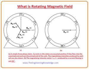
- The principle of rotating field is explained in a simple way by showing the empty stator which has 3 windings that are connected 1200 form each other.
Basic Concept of the Rotating Magnetic Field
- To study the basic principle of rotating field, we will supply 3-phase current the stator of a machine and observe its effect.
- Let’s suppose that the current passing through the three windings of stator is given as.
Iaa’(t) = IMsinwt amperes
Ibb’(t) = IMsin (wt-1200) amperes
Icc’(t) = IMsin (wt-2400) amperes
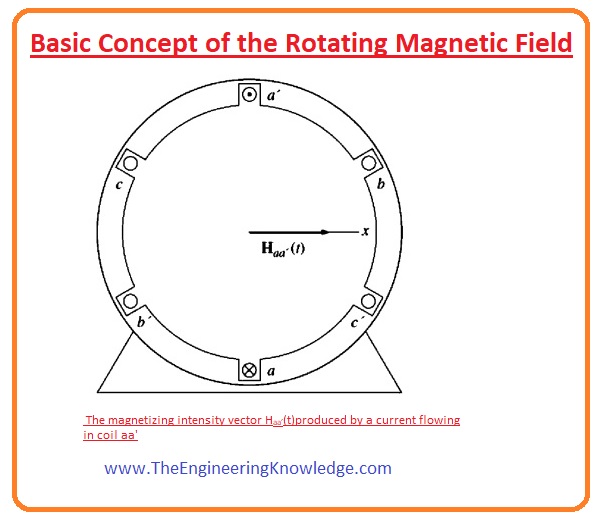
- The current in the winding (aa’) moves in the winding from point (a) and comes out from the point (a’).
- This current generates magnetic field intensity (H).
Haa’(t)= HMsinwt ∠00
- In this equation the 00 is the angle of field intensity (H) vector it is shown in the figure which denoted as.
- The direction of the filed intensity Haa’(t) can be described by the right-hand rule.
- Right Hand Rule says that if we curl our right-hand fingers in the direction of current then the thumb will be in the direction of the magnetic field.
- One point you should note that the magnitude of the magnetic field intensity (Haa’(t)) changes sinusoidally in time, but its direction remains constant.
- Likewise, the magnetic field intensity for the other two windings of the stator is given as.
Hbb’(t)= HMsin(wt-1200) ∠00
Hcc’(t)= HMsin(wt-2400)∠ 00
Flux of the Rotating Magnetic Field
- The flux density of the three currents can found by their field intensities.
- The correspondent fluxes are given here.
Baa’(t)= BMsinwt ∠00
Bbb’(t)= BMsin(wt-120o) ∠00
Bcc’(t)= BMsin(wt-240o) ∠00
- The value of currents and their resultant flux can be found at definite times to measure the correspondent Bnet field on the stator.
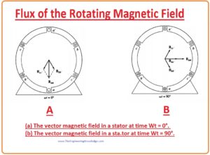
- Let’s suppose at time wt= 0.
- The field at winding (aa’) will be given as.
Baa’=0
- The field density at the winding (bb’) will be.
Bbb’(t)= BMsin(-120o) ∠00
- The field at winding (cc’) will be.
Bcc’(t)= BMsin(-240o) ∠00
- If we add three fields from the windings, then we get the total field at the stator.
Bnet = Baa’(t) +Bbb’ (t)+ Bcc’ (t)
= 0+ (-√3 )/2(BM) ∠1200 + (√3 )/2 ∠2400
=1.5BM ∠-90
- The resultant field is shown in given diagram.
- Let’s take another example and find the value of flux.
- Now take filed at time wt =900
- The values of the current will be.
Iaa’ =IM sin900 amperes
Ibb’ =IM sin (-300) amperes
Icc’ =IM sin (-1500) amperes
- And the value of fields corresponding to these currents will be.
Baa’=BM00
Bbb’=-0.5BM ∠1200
Bcc’=-0.5BM ∠2400
- Now the value of the net field will be sum of these three.
Bnet= Baa’ + Bbb’ + Bcc’
BM ∠00 + (-0.5BM) ∠1200 +(-0.5BM) ∠2400
=1.5BM 0
- The resultant field is shown in the above given diagram and denoted as B.
- You can conclude that from this calculation that the respect of the change in the direction still has same magnitude.
Proof of the Rotating Magnetic Field Concept
- The magnitude of field at any given time has the same value as I.5BM, for practically see this observation we do proof of this statement.
- For this, we see the given diagram, in this figure x and y coordinate is mentioned, x shows right and y upward direction.
- To calculate the net field in the stator we will just sum vectors of the 3 fields of the three windings.
- The total value of stator shown in figure is given as.
Bnet (t) = Baa’ (t) + Bbb’ (t) + Bcc’ (t)
=MBsinwt ∠00 + BMsin(wt-1200) ∠1200 + BMsin(wt-2400)∠240 0
- These 3 fields can be written in the form of x and y components.
Bnet (t) = Bmsinwt x – [0.5BM SIN (wt-1200)]x + [0.866BMsin(wt-1200)]y- [0.5BM SIN (wt-2400)]x- [0.866BMsin(wt-2400)]y
- Now we combine x and y components.
Bnet (t)= BMsinwt – 0.5BMsin(wt-1200) – 0.5BMsin(wt-2400)]+ [0.866BMsin(wt-1200)- 0.866BMsin(wt-2400)]y
Bnet (t)= (1.5BMsinwt) x – (1.5BMcoswt) y
- It is the final equation for the net flux density. Note that the magnitude of the field is constant 1.5BM and the angle varies constantly in a clockwise at angular speed w.
- You can also note that at the wt=0, Bnet =1.5BM∠900
- And at the wt=900 Bnet =1.5BM0
What is the relationship between Electrical Frequency and the Speed of Magnetic Field Rotation
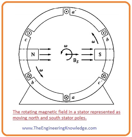
- The given diagram shows the field at the stator can be denoted as north and south poles. It will be north where the flux leaves the stator and there will be south where flux enters in the stator.

- These poles make one rotation around the stator for every cycle of supplied current.
- So, the speed of rotation of the field (rps) is equal to the frequency in hertz.
fe = fm
we = wm
- In these equations, fm and the wm are the mechanical speed in revolutions per second (rpms).
- You can see that the windings on the stator are joined according to this order its anticlockwise.
a-c’-b-a’-c-b’
- The given diagram shows the order of windings in clockwise it is the order of the earlier stator this is repeated two times.
a-c ‘-b-a’ -c-b ‘-a-c ‘-b-a ‘-c-b’
- When we apply 3-phase supply to this stator, 2 north (N) and 2 south (s) poles will be created in the windings of the stator. It is shown in the given figure which is denoted as B.
- The pole of this winding runs only middle of the surface of a stator in one electrical cycle.
- So, the relation among the electrical angle øe and the mechanical angle øm is.
øe = 2øm
- From this equation, we can conclude that the in case of 4 poles winding the electrical frequency of the current is two times the mechanical frequency of rotation.
- Thus, for the four-pole winding, the electrical frequency of the current is twice the mechanical frequency of rotation.
fe = 2fm 4 poles
We = 2wm 4 pole
- In a simple way we have no of a pole at stator is P, then the P/2 repetitions of the windings sequence are ( a-c’-b-a’-e-b’) and the mechanical and electrical terms on the stator have a relation like this.
øe = (P/2) øm
fe= (P/2)fm
We= (P/2)wm
- Note that fm = nm/60,
- By this given equation we can compare the electrical and mechanical frequency as.
fe= (nm/120) P
Reversing the Direction of Magnetic Field Rotation in AC Machine
- There is another fact can be understood about the rotating field is that if we swap the direction of the two currents in the stator then the rotation direction of the field will be changed.
- This shows that we can easily change the direction of motion of the machine by just changing the polarity of the two windings out of three.
- This outcome is solved here and explains the effect of connection change on the magnitude of the field.
- To practical view this observation we change the connections of the phases bb’ and cc’ in given diagram stator.
- The net flux at stator can give as.
Bnet = Baa’(t) +Bbb’ (t)+ Bcc’ (t)
= BMsinwt ∠00 + BMsin(wt-240) ∠1200 + BMsin(wt-120)∠2400
- Now we write this equation in the form of x and y components.
Bnet(t)= BMsinwt – [0.5BMsin(wt-240)]x + [0.866BMsin(wt-240)]y – [0.5BMsin(wt-120)]x + [0.866BMsin(wt-120)]y
- By combining x and y components.
Bnet (t)= BMsinwt – 0.5BMsin(wt-2400) – 0.5BMsin(wt-1200)]+ [0.866BMsin(wt-2400)- 0.866BMsin(wt-1200)]y
Bnet (t)= (1.5BMsinwt)x + (1.5BMcoswt)y
- This time magnitude is also the same, but the direction is clockwise. From this we conclude that we can easily change the direction of ac machine by changing the connection of any two phases of the machine.


