 Hello fellows, I hope all of you are fine. In today’s tutorial, we are gonna have a look at A Simple Loop in Uniform Magnetic Field. There are 2 foremost classes of the alternating current machines, ist is the alternating current motor and 2nd is an alternating current generator. Motor alters electrical energy into mechanical energy and generator converts the mechanical power provided by the prime mover into electric energy. The operating principle of all alternating current machines is very simplest but their complicated construction design makes their working principle understating very difficult.
For easily understanding of the working principle of alternating machines either motor or generator, we will take a loop of wire and put in a magnetic field and relate its behavior with the working principle of the alternating current machines. This simple loop will help us to easy understanding of the working of the alternating machines instead of their difficult structure. So, let’s get started with A Simple Loop in Uniform Magnetic Field.
A Simple Loop in Uniform Magnetic Field
- Before the study of the different AC, machines working principles first, we discuss a simple loop in a magnetic field and how it works.
- A loop in static (uniform) field is like a simple AC machine that generates the voltage like other AC machines.
- A loop working in a uniform field is not totally like the AC machines because the value of flux generated in the AC machine does not remain same, but it fluctuates after some interval of time.
- But the rules and facts which govern the voltage produced and torque of loop also control the voltage and torque of the different AC machines.
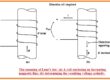
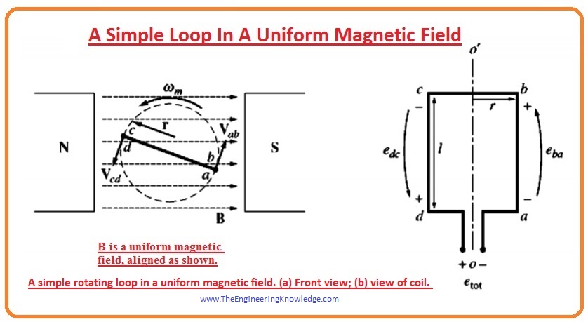
- You can see in a diagram that a machine that has a static magnet represented as north and south which creating a uniform field that originated from the north pole and ends at the south pole.
- A loop of wire is also rotating in the uniform field generated by the magnets.
- The moving part of a machine is known as the rotor, and the static part is known as the stator.
Voltage Induced in a Simple Rotating Loop
- If the loop is moving in the magnetic field, then voltage will be produced in the loop.
- To calculate the value and quantity of voltage look at the figure.
- The loop of wire is rotating in field and give views like the rectangle, which has sides (ab) and cd at 90 degrees to the plane of paper and side (bc) and (da) parallel to the surface of the paper
- In which field the loop is rotating is the uniform and its direction is left to right along the paper.
- To find the voltage induced on the wire loop we will calculate the value of voltage at all sides of loop one by one and add them.
- The value of voltage of every side will find by this given equation.
eind= (V x B). l
- In this equation.
- V is the speed of rotation of the loop.
- B is the field in which loop is rotating.
- L is the length of the conductor.
- By this equation, we can conclude that the emf induced in loop depends on the three factors speed, field, and length of the conductor.
- Now we find the voltage on each side of the loop.
Side (AB):
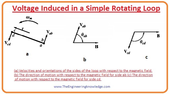
- At this side the direction of the velocity of loop is tangent to the rotating path of loop, while the direction of field is towards the right. It shown in above figure as B.
- The direction of the term (V x B) is into the page which is similar to the direction of side (ab), so the voltage induced at this side is given as.
Eab = (V x B). l
Eab = VBlsinøab into the page,
Side (BC):
- In first half of rotation of this side the term (v x B) has direction into the page and 2nd half its direction is out of the page as the length of loop is parallel to the plane of the page and (v x B) is at 90 degrees to the length (l) so the voltage at this side will be zero.
ecb = 0
Side (CD):
- On this side the velocity is tangent to the rotation path, and the field direction is at right according to the page it shown in the given figure as C.
- The term (v x B) has direction into the page which is similar to the direction of the side CD, hence emf induced in this side is given as.
Ecd = (V x B). l
= VBlsinøcd out of the page,
Side (DA) :
- This side parameter are similar to the (bc), V x B is at 90 degrees to the length of a loop. So emf induced in this side is given as.
eda =0
- The total emf induced in the loop is the sum of emf at its every side now we add them to find the total emf induced.
eind = eab + ecd + eda + ecb
= VBlsinøab + VBlsinøcd
- One point observes that the øab = (1800 – øcd)
- As we know that sinø = sine (1800 – øcd) according to trigonometry.
- Now total induced voltage will be.
eind = 2VBLsinø—(A)
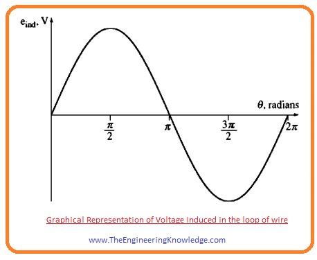
- The graphical representation of total emf induced in the loop is shown in a given diagram.
- There is another method to explain the equation (A) that compares the working of a single loop with the performance of AC machines.
- To find the equation for the machine lets have look at the given diagram again.
- If the loop of wire is rotating at the specific angular speed (w) then the angle of loop enhances with the time linearly.
Ø=wt
- The tangential speed of corners of a loop can be written as.
V=rw
- In this equation, the (r) is the radius of a loop from axis of rotation to the side. And w is angular velocity of the loop.
- If we put the values of angle (Ø) and V in equation (A) then we will have this given equation.
eind= 2rwBlsinwt
- As this loop is behaving like a rectangle so its area is 2rl. So, the new equation of total emf induced will be.
eind =ABwsinwt
- The important thing you can note from this equation is that the maximum flux passes through the loop when the loop at 90 degrees to the lines of flux.
- The equation of flux will be the product of the area of the loop and the flux density of passing through the loop.
- So, the final equation of voltage induced in the loop will be.
eind=ømaxwsinwt—- (B)
- From this equation, we can conclude that the voltage induced in the loop is sinusoidal and its magnitude is the multiple of flux and the velocity at loop is rotating in the field.
- This also happens in the case of real AC machines.
- In simple words, the voltage induced in any machine will depend on the 3 parameters.
- The flux in the machine.
- Speed of rotation.
- The no of loops in the machine.
Red also
- Difference between Electric & Magnetic Field
- Faraday’s Law-Induced Voltage From Time-Changing Magnetic Field
- What Is Magnetism? | Magnetic Fields & Magnetic Force
- What is Rotating Magnetic Field
That is the complete tutorial on A Simple Loop in a Uniform Magnetic Field, I hope all of you have understood the working principle of any ac machine by comparing it with the loop working principle. If you still have any question please mention in the comments. I will resolve your queries. See you in the next tutorial Torque Induced in a Current-Carrying Loop.