Hi guys, welcome to the new post. Here we will discuss the circle diagram of an induction motor—its definition, construction, and its parts. In the electrical engineering world, the circle diagram of the induction motor is the main parameter that is used to study and analyze the working of this device. In this post, we will discuss different parameters for a circle diagram. So let’s get started with what the Circle Diagram of Induction Motor is.
What is a Circle Diagram of an Induction Motor?
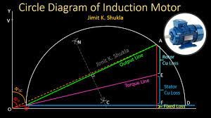
The circle diagram is a technique that denotes the performance of the induction motor in the form of a graph. The circle diagram of induction motors offers details of different parameters of motors, like starting torque, losses, efficiency, high output power, slip, maximum torque in motors, and other factors.
The circle diagram method is used for denoting and analyzing induction motor working since it is simple and easy to make. It can be made with the equivalent circuit of an induction motor.
The no-load test and blocked rotor test are done on the induction motor for making the circle diagram. So we can define a circle diagram of an induction motor as a diagram that is made with the locus of current taken with the induction motor for different parameters, known as a circle diagram of an induction motor.
Circle Diagram Importance
The diagram gives details that are normally not provided with a normal phasor diagram. The phasor diagram provides the relation between current and voltage under single circuit conditions.
If the condition varies, there is a need to make a phasor diagram. But a circle diagram can be defined as a phasor diagram in a single plane for more than one circuit condition.
What is a slip ring, and what are its types and applications?
Read also: DC Motor Starters and Circuit Diagram
Test for finding Data Required for Drawing Circle Diagram
From the no-load current and angle between voltage and current used for drawing a circle diagram, it is measured.
The angle will be larger in no-load conditions; induction motors come with high inductive reactance.
If the block rotor test is performed, the rotor is blocked, which is like a short circuit secondary of the transformer. In this test there is a need to measure short circuit current and lag angle between voltage and current for making a circle diagram. With that there is a need for rotor and stator copper loss.
Construction of Circle Diagram of Induction Motor
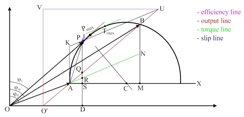
- Set the scale and make vector OZ that is equal to no-load current I0, and the phase angle according to the vertical axis is φ0.
- Now make horizontal line AX.
- After that, Vector OB is equal to short current (ISN) related to the normal supply voltage, and the phase angle with the vertical axis is φsc, and join AB is made.
- Now make a 90-degree bisector with line AB, which joins horizontal line AX at point C.
- Suppose point C is the middle and draw part of the circle through points A and B. This part of the circle is the locus of the input current and makes a circle diagram of the induction motor.
- From point B, make a vertical line BM to join line AX, and divide BM to point N.
- For the given operating point P, make vertical line PQRSD.
- If there is a tangent drawn to the circle diagram parallel with the output line and torque line, then points where these two tangents meet the circle diagram denote points of maximum power and maximum torque.
Read also:
- Different Types of Induction Motor and Features
- Difference between Induction Motor and Induction Generator
- Difference Between Single Phase and Three Phase Induction Motor
- Difference between Synchronous Motor and Induction Motor
- What is the No Load Test of Induction Motor
- Single Phase Induction Motor Starting Methods
FAQs
What is a circle diagram in induction motors?
The circle diagram is a graphical denoting of the performance of an electrical motor made in the form of a locus of motor input voltage and current. It was first made by Alexander Heyland in 1894 and Bernhard Arthur Behrend in 1895.
Which of the following is required to draw the circle diagram for an induction motor?
The no-load test and blocked rotor test are used for making a circle diagram.
What is a 3-phase slip ring induction motor?
It is made with a laminated cylindrical core that comes with a semi-closed slot at the external periphery and has three-phase insulated winding. The rotor is wound with the same poles as the stator. Making a star point, 3 complete terminals are connected.
Is the induction motor AC or DC?
The induction motor, or asynchronous motor, is an AC electric motor where current in the rotor is generated by torque through electromagnetic induction through the magnetic field of the stator winding.
What is the induction motor principle?
The motor operated on an electromagnetic induction principle called induction motor. Electromagnetic induction is a process in which electromotive force is induced over the electrical conductor when it is put in a rotating magnetic field.
Why is it called an induction motor?
The relative speed between the stator RMF and rotor conductors resulted in induced emf in rotor conductors, on the basis of Faraday’s law of electromagnetic induction.
Rotor conductors are short circuits, and rotor current is generated due to induced emf. So these motors are called induction motors.
What is the torque of a motor?
The torque output of the motor is the rotational force that the motor generates. The torque of a small motor is measured in inch-pounds (in-lbs), Newton meters (N-m), or other directly transformed units of measure.
What are induction motor types?
Induction motors are defined in two types: single-phase induction motors and three-phase induction motors.
The one-phase induction motor is connected to a single-phase AC supply, and three three-phase induction motors can be connected to a three-phase AC power supply.
What is a 3-phase motor?
The 3-phase motor is an electric motor that gets power from a three-phase system. It can be done through a 3-phase main supply or frequency inverter. 3-phase motors are synchronous and asynchronous motors.
What is the DOL starter?
DOL motor starting is used when the motor is started at full load, with full line voltage connected with motor terminals. It causes the motor to use a larger current and is best for motor powering to 4KW, with a high motor size of 10KW connected.
What is a stator and rotor?
The stator is the static part of an AC motor, and the rotor is the rotating component of the motor.


