 Hi reader I hope you all are doing great in this post we will have a detailed look at Equivalent Circuit of Single Phase Induction Motor. Single-phase induction motor is a type of motor that operates at a single phase. This is an ac motor that needs an ac signal to operate. There is a different use of this motor in industries and homes to run the load.
In this post, we will cover details about its equivalent circuit and related terms that operate. So let’s get started with Equivalent Circuit of Single Phase Induction Motor.
Equivalent Circuit of Single Phase Induction Motor
- To get an understanding of the torque induced in the single-phase induction motor there is a need to study the double-revolving field theory or cross-field theory of single-phase induction motor.
- Each of them will help to discuss the equivalent circuit of the motor and torque-speed characteristics of the motor.
- Here we will discuss the double-revolving field theory to find the equivalent circuit of an induction motor.
- In this tutorial, we will make an equivalent circuit of the main winding of a single-phase induction motor in case of there is no load link to it.
- The method of symmetrical elements is compulsory to study the single-phase motor having main and auxiliary windings.
- The finest method to start the study of a single-phase induction motor is to take analyze the motor in the installed state.
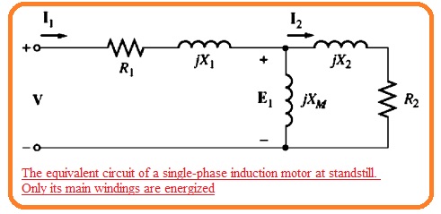
- At this time motor looks to operate like the single-phase transformer having secondary circuitry in short form and its equivalent circuit is like the transformer.
- The resultant circuitry can be seen here.
- In this circuit R1 and X1 are the resistance and reactance of winding exit at stator XM denotes the magnetizing reactance and R1 and X2 denote the referred values of resistance of rotor and reactance.
- The core losses of the motor are not taken here and will be added to the mechanical and stray losses as a combination of rotational losses.
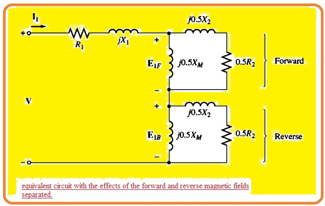
- As we know that the pulsating air gap flux in the motor in case of stall conditions can be divided in 2 equal and reverse fields in the motor.
- As these fields have similar dimensions and everyone is participating in equally the resistive and reactive voltage loss in the cirucit of rotor.
- It is certain to divide the rotor equivalent circuitry in 2 parts every part is corresponding to the effect of one field.
- The motor circuit having the fact of forward and reverse magnetic field can be seen here.
- Let us assume that the rotor of the motor starts to operate through the auxiliary winding and when motor gets the required speed winding will be removed.
- The value of effective rotor resistance of induction motor relies at the quantity of relative motion among the rotor and stator field.
- Though there are 2 fields in the motor relative quantity of relative motor different from them.
- For the forward field, the per unit difference between the rotor speed and the speed of the field is called slip S here slip definition is similar to the three-phase induction motor.
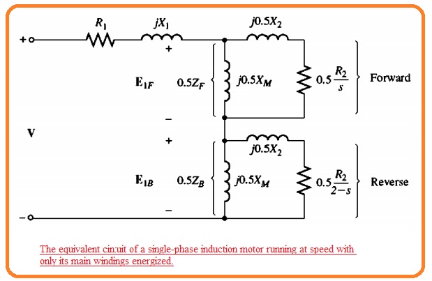
- The resistance of rotor in this portion of the circuit related to the forward magnetic field has a value of 0.5R2/s.
- The forward magnetic field revolves at speed nsync and the reverses field revolves at -nsync. So the net per unit difference among the forward and reverse fields has a value of two.
- As the motor is rotating at a speed less than the forward field the total per unit difference in speed among the rotor and reverse field is 2-s.
- So the effective rotor resistance in the portion of circuitry related to the reverse field is 0.5R2/(2-s).
- The complete induction motor equivalent circuit can see here.
Circuit Analysis of Single-Phase Induction Motor Equivalent Circuit
- The single-phase induction motor equivalent circuit in the above figure is like the three-phase equivalent circuitry with the difference that it comprises of both forward and backward elements of power and torque.
- The similar power and torque relation which applicable for the three-phase motor also applicable for any forward or backward element of a single-phase motor and total power
- The single-phase induction motor equivalent circuit in Figure 10- 28 is similar to
the three-phase equivalent circuit, except that there are both forward and backward components of power and torque present. 1lle same general power and torque in motor is a difference among the forward and reverse elements.
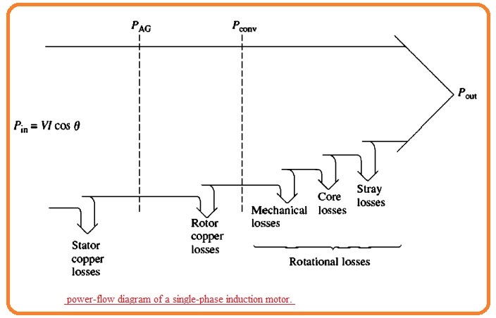
The power flow figure of the induction motor is shown here.
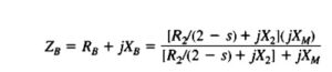
- To do the mathematical form of the input current passes in the motor it is necessary to explain impedance ZF and ZB here ZF is the single impedance equivalent to all the field impedance components and ZB is one impedance equivalent to the backward field impedance component.
- The value of impedance is given here.
![]()
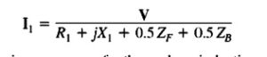
- In terms ZF and ZB the current moving in the induction motor stator winding is given here.
- The per-phase air gap power of the three-phase induction motor is the power used in the rotor circuitry resistance0.5R/s.
- Likewise, the forward air gap power of a single-phase induction motor is the power used 0.5/R(2-s).
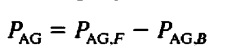
- So the air gap power of the motor can be found by measuring the power in the forward resistance 0.5R/s finding the power in the reverse resistance 0.5R2/(2-s) and subtracting one another.
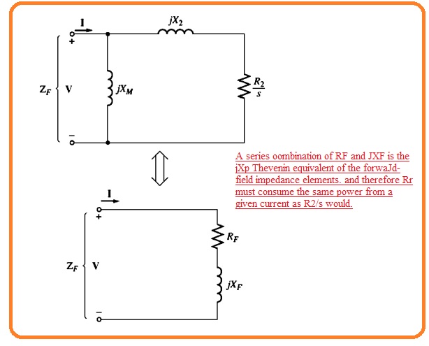
- The most difficult portion of this measurement is to find the distinct current passing in the 2 resistances. But luckily the simplification process of the equation exists.
- Note that the only resistance in the circuit components comprising the equivalent impedance ZF is the resistance R2/s.
- So ZF is equivalent to the circuitry any power used by ZF should be used through the real circuitry and so R2.s is only resistant in the real circuitry its power usage should equal to the impedance of ZF.
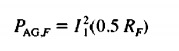
- Do the air gap power for the forward magnetic field can be explained here.
- So the air gap power for the reverse field can explain here.
![]()
- The benefits of these 2 above equations is only the current I1 and required to find both powers.
- The net air gap power in single-phase induction motor is given here.
- The induced torque in a three-phase induction motor can be given here.
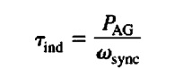
- Here PAG is the total air gap power given in the above equation.
- The rotor copper losses can be calculated as the summation of rotor copper losses caused by the forward field and rotor copper losses due to the reverse field.
![]()
- The rotor copper losses in the three-phase induction motor are equal to the per-unit relative motion among the rotor and stator field time of the airgap power of the motor.
- Likewise, the forward rotor copper losses single phase motor is given here.
![]()
- The reverse rotor copper losses of the motor is given here.
![]()
- As these 2 power losses in the rotor has different frequencies the net rotor power loss is a summation.
- The power transformed through electrical to mechanical form in a single phase induction motor is given by a similar equation.
- This equation is
Pconv=Tindwm
- Since Wm = (1 – s)wsync, this equation can be defined as
PCov = Tind(1 – s)wm
PConv = (I – s) PAG
- In the case of a three-phase induction motor, the shaft output power is not similar to the Pconv so the rotational losses should be minus.
- In the single phase induction motor used here the core losses, mechanical losses, and stray losses should be mined from Pconv to gett Put.