 Hi, readers welcome to the new post. In this post, we will have a detailed look at DC Motor Starters and Circuit Diagram. DC motor is a device that uses dc power for the creation of mechanical power. There are numerous types of dc motor such as shunt dc motor, series dc motor, compound dc motor. These are motors are described according to their construction and torque generation.
In this post, we will different methods used to required for stating of dc motor and their resultant effects. So let’s get started with DC Motor Starters and Circuit Diagram
DC Motor Starters and Circuit Diagram
- For the accurate operation of dc motor, there must be some controlling circuit and protective devices are required to link with it to operate. These devices link to the dc motor has these 4 main purposes.
- Provide protection to the motor from damage due to a short circuit.
- It provides protection to a motor from overloads condition for a long time.
- It saves the motor from starting high current.
- These devices help to control the speed of the motor in the easiest way.
DC Motor Problems on Starting
- For the accurate operation of the motor, it should be retained safe physical construction when it started.
- When the motor has starting conditions there is no movement in its rotor so it value of internally generated voltage is zero.
- As the value of inner resistance of dc motor is less than its physical dimensions so a large current passes through it.
- Let us suppose that we have fifty Hp motor having operating volts are two-fifty. The value of armature resistance is the 0.06-ohm value of the full load current is two hundred amperes so the starting current will be for this motor.
IA=(VT-EA)/RA
(250V-0V)/0.06
4167A
- The value of this current is two times more than the rated full load current of the motor. This current can cause serious problems for the motor.
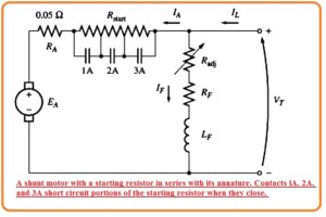
- The solution for this high current during starting is to place starting resistance in series to the armature winding the limit the current till the point then EA generated that reduce this current.
- The connected resistance not to be for a long time since it causes power losses and also disturbs the torque-speed curve with the load increment.
- So resistance should resistance linked with the armature to stop current then remove it till then motor gets the needed speed.
- Currently used starting resistance consists of different parts that removed from the circuitry with the increment if motor speed.
- The below figure indicates the shunt motor link to the starter resistance which will be removed from the circuitry in parts with the closing of contents lables as 1A, 2A, 3A.
- For use of starts, there must be two conditions fulfills. The first one is to choose numbers and resistances parts required to make limiting circuitry.
- The 2nd one is to make a control circuitry while making the connection at the accurate time to eliminate resistance segments.
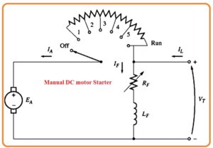
- In older motors, such states are used that will be removed from the circuitry manually by the man that rotates the handle.
- The working of this starter depends on the person handling this starter either he moves this handle at an accurate time or not.
- If he removed the starters very early then motors get the required speed then a large current will flow in the motor.
- While man removed the resistance from the circuit very slowly then starting circuitry resistance can burn out.
DC Motor Starting Circuits
- After selecting the starting resistance for close their contacts different methods are used here we discuss two commonly used techniques.
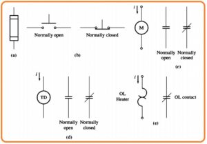
- In below figure you can see the components of motor control circuitry. Here fuse, pushbuttons switches relay, time delay relay, and over loads are the main parts of the circuitry.
- the figure denoted as a shows the symbolic representation of fuse. This fuse will help to prevent the motor from short circuits.
- These fuses are linked lines in series through which the current passing to the motor.
- If a short circuit occurs then fuse in that line will burn out and break the circuit and save the motor.
- The figure denoted as b indicates the spring category of push-button switches. Here 2 main types of switches used the first one normally open and the second one normally shut.
- Normally open contacts will be open when the button is open and become closed when the button is closed or push and normally closed contacts are closed when the button is a push.
- The relay can be seen in a figure denoted as c. It comprises of the main coil and the number of contacts.
- The main coil is denoted with a circle symbol and contacts are shown as parallel lines.
- There are 2 categories of contacts first one is normally closed and the second one is normally open.
- Normally open contact is open when the relay becomes energized and normally closed contact is closed when the relay gets deenergized
- In case when there is a power given to the relay its contacts vary their state normally open contacts become close and normally closed contacts become open.
- In the figure denoted as e overload is shown. It comprises of heater coil and normally shut contacts. The current passing to the motor also flows by this heater windings.
- If current from the motor is very high then-current passing through the motor will heat up the heater that results normally shut contact of overload to become open.
- The contacts can activate different categories of motor protection circuits.
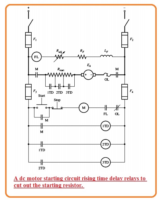
- In below figure the motor starter circuit created with the above-explained components has shown in below figure.
- In this circuitry series of time relay shut contacts that eliminate every part of starting resistance at an almost accurate time when power is given to the motor.
- If we push the start button of the circuitry the armature circuitry of motor is linked to the power supply and motor will initiate its operation will all resistance in circuitry.
- Though 1TD relay becomes energized with the motor starting after some delay its contacts will be closed and remove eliminate part of starting resistance from the circuitry.
- With this relay, 2TD will become energized after the second delay contacts of 2TD become closed and eliminate 2nd portion of resistance.
- After closing the 2TD contacts 3TD relay becomes energized.
- This procedure is repeated again and at last, motor operates at full speed and no resistance is linked to the circuits.
- if the time delay is accurately given the starting resistance can be removed at an accurate time to restrict the current of motor at its designing parameters.
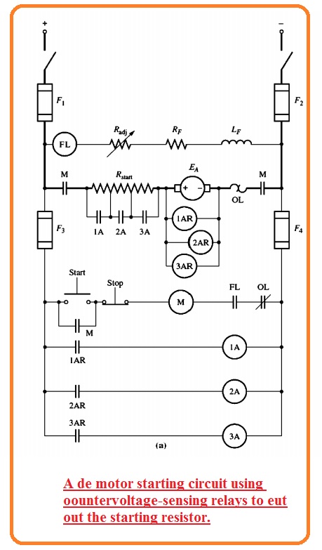
- Another category of starter motor can be seen here.
- In this circuitry, the relay detects the value of EA of the motor and removes the resistance from the circuitry when the value of EA is at a set value.
- This started circuitry is better than earlier discussed if a motor is connected to high load and operates slowly then normal speed its RA will remove from the circuitry when current drops to a certain level.
- Note that both starter circuitry has a relay in field circuitry denoted as FL. It is known as field loss relay.
- If due to certain reason field current losses the field loss relay become deenergized that cut off the power to the relay M.
- When relay M is in a de-energized state it normally opens contacts and separated the motor from the power source.
- This relay is provided protection to the motor in case of IF is not present.
- Note that ie overload exists in every motor starter circuitry. If the power flowing from the motor becomes high then open the OL normally closed contacts, it causes the M relay to off.
- when the M relay is not energized it normally open contacts open and disconnect the motor from the power source that provides motor protection from damage due to overload.
That is a detailed post about DC Motor Starters and Circuit Diagram. If you have any further query ask in the comments. Thanks for reading. Have a nice day.


