 Hello, fellows, I hope all of you are enjoying your life. In today’s tutorial, we will have a look at the Voltage Current Characteristics of Diode. The diode is 2 terminal semiconductor devices that are used to rectify alternating current into the direct current. If it converts a half-wave of alternating current into direct then this process is called half-wave rectification. If convert both parts of alternating current into direct current this process is known as full-wave rectification. In almost every electronic device and engineering project, a diode is used such as ups and some other electronic projects. There are different types of a diode according to their construction and working such as LED, OLED, Zener, etc.
There are normally 2 methods are used to provide input supply to the diode first is forward biasing and the second is reverse biasing. If the positive terminal of the battery is connected with the anode and the negative terminal is connected with the cathode this type of bias is known as forwarding bias. If the negative terminal of the battery is connected with the anode of the diode and the positive is connected with the cathode this called reverse biasing. By using these to biasing we will discuss the effect of current and voltage across the diode and find different characteristics. So let’s get started with the Voltage Current Characteristic of Diode.
Voltage Current Characteristic of Diode
- For a practical understanding of V-I characteristic of a diode, we discuss the forward biasing and reverse biasing conditions one by one.
V-I Characteristic for Forward Bias
Note: In this post, there are 2 types of voltage that will be discussed the first one is froward biased voltage and the second is forward voltage (VF). The difference is that forward-biased voltage across the complete circuit is provided by the external voltage source. While forward voltage (VF) is the only value of voltage across the diode in a circuit. Let’s start.
- The current flows when the diode is forward is called forward current. In the given figure this current is denoted as IF.
- In the given below figure, there are 2 circuits shown for forward-biased arrangements
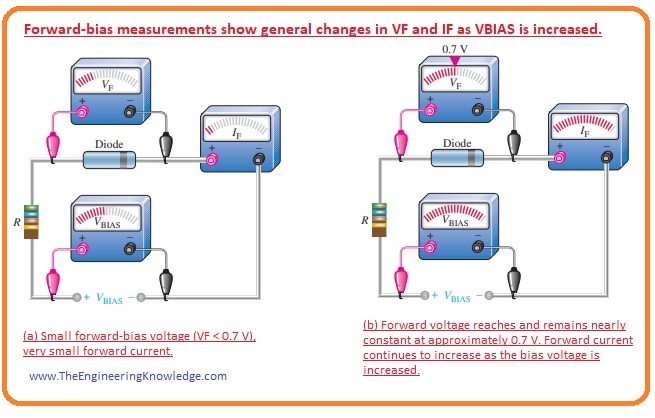
- In this circuit, we will increase the value of voltage from the 0 across the diode and will find the effect on it.
- In the circuit, resistance is connected in series it is used to limit the value of current passing through the circuit to save a value that will not damage the diode.
- At the start, there is no voltage across the diode as we increase the forward-biased voltage value the current IF and voltage across the diode increases the value of forward current and voltage across the diode can be seen in an ammeter and voltmeter connected in a circuit.
- This arrangement is shown in the above circuit denoted as a.
- Some value of forward biased voltage is loss across the limiting resistance.
- In the above figure, the circuit denoted as b explains the condition when the value of forward biased voltage is such that the voltage across the diode is almost 0.7 volts or potential barrier while the increment in value of forward current is very fast
- As we continuously increase the forward-biased voltage-current also increases very fast with the forward-biased voltage, but the voltage about the dido increases very slowly after the 0.7 volts that are potential barriers.
- The less increment in the voltage across the diode after 0.7 volts is due to the voltage loss across the internal resistance of the semiconductor material by which the diode is constructed.
V-I characteristic curve for a forward-biased diode
- If shown above circuit measurements on the graph this graphical representation is called the V-I characteristics curve for a forward-biased diode.
- In the below figure this graphical representation is shown.

- You can see in the graph that is denoted as a that VF forward voltage or voltage across the diode is along the x-axis and (IF) forward current is along the Y-axis.
- In the graph (a) you can see that there is very less increment in the forward current (IF) till value of forward voltage is 0.7 volts.
- After the 0.7 volts of forward voltage the increment in the forward current is very fast and (VF) is almost constant.
- The increment in forward voltage is less due to internal resistance or dynamic resistance voltage drop and forward continuously increases.
- In the curve (a) you can see three different points A, B, and C. First point ‘A’ explains the zero biasing condition.
- ‘B’ is a point where the value of forward voltage or VF is less than the potential barrier or 0.7 volts.
- While point ‘C’ defines the position where the forward voltage equals the potential barrier or 0.7 volts.
- After point C or knee of the curve, the increment in forward current is large while in forward voltage increment is minor.
- In practice, the value or forward voltage is almost one volt according to the value of forward current.
Dynamic Resistance
- The given figure is the expended form of V-I curve for forward bias diode and it explains the dynamic resistance.
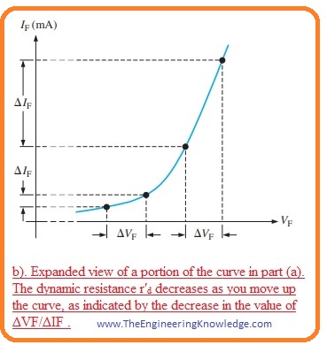
- As linear resistance has a constant value but the value of resistance offered by the diode in forward biasing does not remain the same throughout the forward biasing diode.
- This resistance is known as ac resistance or dynamic resistance.
- Interior resistances of electronic components are generally labeled by lowercase italic r with a prime, in its place of the R.
- The dynamic resistor of the diode before the knee of the curve is high since the increment in current is very low with the increment in the voltage.
- As the voltage approaches to knee the curve resistance starts to decrease and after the knee point it becomes much less and the current starts to increase.
V-I Characteristic of Diode for Reverse Bias
- When the diode is in reverse biasing condition then the current (IR) flow is very less.
- When the voltage across the diode is zero the IR is also zero.
- With the increment in reverse-biased voltage then very less value of reverse current flows through the diode and voltage across the diode is also less.
- If we continuously increase the voltage applied then if the value of reverse voltage across the diode is equal to the breakdown voltage (VBR) then the reverse current flows very rapidly.
- With the further increment in the reversed biased voltage, the reverse current also increases continuously but the increment in the voltage across the diode is very less.
V-I Curve for Reverse Biased Diode
- If we make a graphical representation of reversed biasing of a diode. The curve obtains is called V-I characteristic curve for a reverse-biased diode.
- In the given figure, you can see the graphical representation.
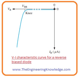
- In the curve, you can see that the reverse voltage (VR) across the diode is drawn on the negative X-axis and the reverse current (IR) on the negative Y-axis.
- The increment in the reverse current is very less till the point where reverse voltage is at the knee point.
- After the knee of the curve reverse voltage is almost the same but the reverse current increases very fast.
- If the value of reverse current is not controlled then it can overheat or damage the diode.
- The doping level of decides the breakdown voltage of the diode, the doping level of the diode is set by the diode’s manufacturer.
- Normally general purpose diode has a breakdown voltage value larger than fifty volts and some special diodes have a breakdown voltage of almost five volts only.
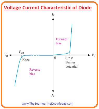
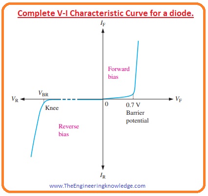
Complete V-I Characteristic Curve of Diode
- If we combine both forward-biased and reverse-biased curves of dido than we have a complete V-I characteristic curve. It is shown in the below figure.
Temperature effect on diode V-I characteristic
- If a diode is forward biased and we increase the temperature then there will be an increment in the forward current IF at a specified value of forward voltage.
- With the increment of temperature forward voltage decreases at a certain value of current.
- The effect on the diode V-I curve is shown in the given figure.
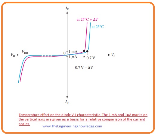
- You can see there are 2 curves in the graph blue is at room temperature (25 centigrade) and the red curve is for increment in the temperature (25C +ΔT).
- With the increment in one degree Celsius, the potential barrier decreases by two millivolts.
- If the diode is in reverse biasing conditions then the increment in temperature of the reverse current (IR) also increases.
What are the different types of diodes?
There are different types of diodes, like
- Silicon diodes
- Germanium diodes
- Zener diodes
- Tunnel diodes
- Light-emitting diodes (LEDs)
- Photodiodes
- Varactor diodes
- Schottky diodes
Read Also:
- The current-voltage characteristic or I–V curve is a graphical denotation between the current of the circuit and the corresponding voltage, or potential difference.
- VI characteristics of P-N junction diodes is the curve between voltage and current in the circuit. Voltage is at the x-axis and current at Y axis.
- Diodes are semiconductor devices that work only for current to flow in a single direction. it can seen in the I-V curve.
- For positive voltage curve increases exponentially denoting current is free to flow in the device. At negative voltages, the current is zero.
- linear V-I characteristics come with a straight line in the graph that passes through the origin. The line between the X-axis and the Y-Axis comes with a constant slope that defines the resistance of the component is constant. Linear V-I characteristics for a component can be for a particular region.
- The ideal diode comes with the same characteristics curve as an ideal switch, that works when potential is provided and an open circuit when no supply is connected. it means the ideal diode has zero resistance in forward bias and infinite resistance in reverse bias
What is voltage at diode?
| Type | Forward threshold voltage |
|---|---|
| Silicon diodes | 0.6 V to 0.7 V |
| Germanium diodes | 0.25 V to 0.3 V |
| Schottky diodes | 0.15 V to 0.45 V |
- The diode is a component that is used for converting AC to dc. Diodes are used in rectifier circuits for converting ac to DC. Diodes are used to protect a circuit from reversing currents and to regulate voltage in a circuit.
So friends that is the detailed post on the Voltage Current Characteristic of the Diode if you have any further queries ask in the comments. Thanks for reading. See you in the next post. Have a good day.


Educative article, learned a lot from this report.
So glad I found your blog, and was able to learn new things.
Keep posting articles that are informative, it’s really valuable.
Best regards,
Lunding Schneider
I quite like reading through an article that can make
people think. Also, thanks for permitting me to comment!
Wonderful article! This is the type of info that are meant to
be shared across the web. Shame on Google for no longer positioning this submit higher!
Comee on over and consult with my site . Thank you =)