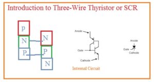
 Hello, readers welcome to the new post. in this post, we will have a detailed look Introduction to Three-Wire Thyristor or SCR. The thyristor is 4 layer consisting of 3 terminals device. The layers of these modules are in N and P configuration having two PN junctions. The two main terminals of these modules are anode and cathode. There is a third terminal that used as a control terminal called a gate is linked at the p material close to the cathode terminal.
In this tutorial, we will cover details about its working, operation, and some other related factors. So let’s get started with an introduction to Three-Wire Thyristor or SCR.
Three-Wire Thyristor or SCR
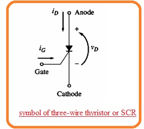
- The SCR stands for silicon controlled rectifier that belongs to the thyristor groups having three terminals anode-cathode and gate.
- It was created by the general electric company in 1958 and the name are given by this company. The symbolic representation of SCR can be seen here.
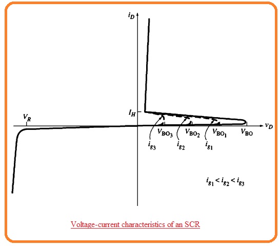
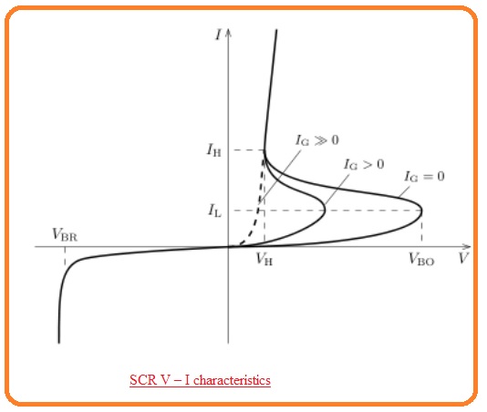
- According to its name, it is inferred that SCR is a controlled rectifier or diode. The voltage-current characteristic of this device having a gate terminal open circuit is like to the PNPN diode.
- The thing that caused it to fruitful for use in motor control applications is its break over-voltage that can e regulated through current passing in its gate terminal.
- There is an inverse relation between gate current and VBO if gate current is larger than VBO is decreased,
- If SCR is selected there is breakover voltage with zero gate signal is greater than the highest voltage in the circuitry so it can be operated through the usage of gate current.
- When it gets on the component remains on till its current is less than IH.
- So when SCR is get triggered then its gate current is eliminated without disturbing the on condition of this component.
- In the on the condition, the forward voltage loss about SCR is 1.2 to 1.5 volts larger than the voltage loss about normal forward-biased diode.
- SCR is a generally used component in power control circuitry. It mostly used in switching and rectifier circuits and generally its rating values are three thousand amperes.
SCR Parameters
- It gets on when the voltage VD gave is larger than the VBO.
- Its breakover voltage VBo is regulated through the current passing in the gate of SCR.
- It gets on when ID current is less than the loss through IH.
- It stops all current passing in reverse direction till extreme reverse voltage gets.
Gate Turnoff Thyristor
- With the passage of time, there is betterment in the thyristor structure is done and in result, gate turnoff thyristor is designed. The GTO thyristor is SCR which gets off through a high negative pulse provided at its gate terminal when it gets become larger ID than IH.
- Though GTO thyristor was created in 1960 but first time used in 1970 for motor control applications.
- It generally and commonly used in motor control circuits as they reduce the requirement for exterior elements to off SCr in dc circuitry.
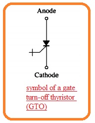
- The symbolic representation of GTO thyristor can see here.
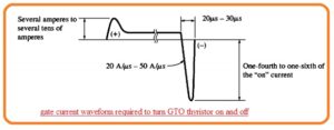
- The below-shown diagram indicates the normal gate current signal for high power GTO thyristor.
- The GTO thyristor generally needs a high gae current to get on than normal SCR.
- For high power usage components gate current values are of twenty to thirty microseconds.
- The magnitude of negative current pulse should be 1/4 to 1/6 which the current passing through components.
SCR Switching characteristics
- In a normal thyristor when it gets on through gate then it retains in on condition causing anode current larger than latching current IL.
- When an anode is in a positive biased state it does not off till the current loss to less than IH or holding current.
- In general operation state the latching current is larger than IH.
- In below figure the IL is larger than IH at y-axis because of IL> IH.
- The thyristor can become off if exterior circuitry results at anode to become negatively biased.
- In certain applications, it is done by switching the 2nd thyristor to do discharging the capacitor in the anode of ist thyristor.
- This process is known as forced commutation.
- When the current in thyristor is eliminated the finite time delay should exist before the anode again positive biased state and maintain the off condition.
- This minimum delay is known as circuit commutated turn-off time.
- Causing the positive bias anode in this time results in the thyristor becoming self-triggered through existing charge carriers holes and electrons.
That is a detailed post about SCR if you further want to get about SCR ask in the comments thanks for reading. See you in the next post. Have a nice day.


