 Hello, readers welcome to the new tutorial. In this post, we will have a detailed look at Introduction to Pulse-Width Modulation Inverters. PWM or pulse width inverter is the new type of inverters that is the replacement of older types of inverters. Generally, it employed in different types of power electronics circuitry. In this circuitry, there is the use of MOSFET to work as a switch at output terminals.
Pulse width inverter is a type of inverter that works at the PWM techniques so its called pulse width modulation inverter. These modules used to sustain the output voltage according to the rated value of voltage according to the country to provide to load required voltage. In this post, we discuss its working, circuitry, and other related parameters. So let’s get started with Introduction to Pulse-Width Modulation Inverters.
Introduction to Pulse-Width Modulation Inverters
- Pulse-width modulation is the way through which the width of the pulse is modified in direct relation to the small value control signal if the control signal has a large value then there will be wider width of the consequent pulse.
- Through the use of required voltage frequency in form of control voltage for PWM circuitry it can generate a large-signal waveform that has average voltage variation in sine waveform in a method that is good for running ac motors.
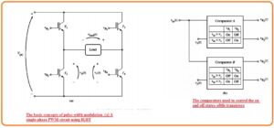
- In the below figure you can see the simple operation of Pulse width modulation.
- The figure denoted as a indicates single phase pulse width modulation inverter circuitry that consists of IGBT.
- The state from IGBT1 to IGBT5 in this circuitry can be regulated through the use of 2 comparators can see in figure b.
- The comparator is an instrument that used to compares the input voltage Vin(t) to reference voltage and on and off the transistor according to the outcomes of testing.
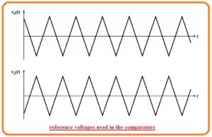
- Comparator denoted as A do comparison among the Vin(t) with the reference voltage Vx(t) and regulate the IGBT T1 and T2 according to the consequence of comparison.
- The comparator B do comparison among the Vin(t) to the reference voltage Vy(t) and regulate the IGBT denoted as T3 and T4,
- If the value of Vin(t) is larger than Vx(t) at a certain value of time in results the comparator denoted as A will get on T1 and off the T2.
- In the opposite case, it will off the T1 and on T2. Like this process, if the value of Vin(t) is larger than Vy(t) for a certain value of time then comparator B will on the T4 and off the T3
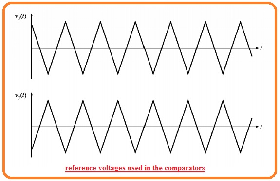
- In the opposite case, it will on T3 and off T4. The reference voltage Vxt and Vyt can seen here.
- For understanding the complete working of this pulse width modulation circuitry we observe that what will come out if a different value of regulated voltage is given.
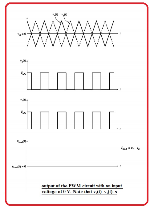
- First of all suppose that the value of control voltage is zero.
- The voltage Vxt and Vyt has similar value and load voltage circuitry is zero volts.
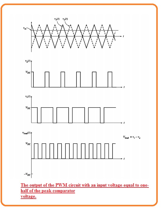
- After that suppose that constant positive control voltage is similar to half the value of the peak reference voltage is given to the circuitry.
- The outcome voltage is a train of a pulse having fifty percent duty cycle can seen here.
- At last suppose that sine wave control voltage is given to the circuitry can see here.
- The width of the resultant pulse train changes sine waveform according to the control voltage.
- The outcome is a high power output signal that has an average value over the small area is in direct relation to the average voltage of the control signal area.
- The fundamental frequency of the output signal is like the frequency of input control voltage. So there is harmonic elements exist in the output voltage that not affect the motor control functions applications.
- The Harmonic elements can results in extra heating in the motor that is operating through the use of an inverter but the additional heating effect can be controlled through the use of a certain type of motor or derating the working normal motor. mean operate this motor less than the rating power.
- The net 3 phase PWM inverter comprises of 3 single-phase inverters having control voltage comprising of the sine wave having one twenty degree angles.
- Frequency regulation of in this category of PWM of this inverter is done through varying the frequency of input control voltage.
- The PWM inverter changes condition numerous times through one cycle of the resultant output voltage.
- During this time reference voltage having a frequency close to the twelve kile hertz that used in PWM inverter construction therefore in PWM inverter should vary condition twenty-four thousand times in single seconds.
- This fast switching indicates that PWM inverter needs faster elements than CSI or YSI.
- PWM inverter required high power high-frequency elements like GTO thyristor.
That is a detailed post about PWM if you have any further query ask in the comments. Thanks for reading. Have a nice day. See you in next post.

