 Hello, friends welcome to the new post. In this post we will have a detailed look at Introduction to Pulse Circuits. The purpose of any signal is not to transmits the data and information also explains about that the operation of any circuitry. The operation of any circuitry can be understood through the signal that it generated through the circuitry.
In this post we will overlook different pulse circuits and different parameters related to Pulse circuits. So let’s get started with Introduction to Pulse Circuits
Introduction to Pulse Circuits
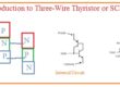
- The SCR GTO thyristor and TRIAC are generally getting on through the use of pulse of current at their gates. All these components has been discussed in detail in previous posts.
- For the creation of power controllers, it is compulsory to offer some techniques for creating and applying pulses at the gates of such modules at a certain time on the devices.
- With that, it is compulsory to offer certain techniques for the generation and application of negative signals at gates of GTo thyristors at certain times to gets off.
- Numerous methods exist to generate voltage and current pulses. These can be parted in 2 main types analog and digital/
- Analog pulse production circuitry has used from the creation of solid-state machine controls.
- They normally depend at the components like PNPN diode which has voltage-current characteristics having distinct non-conducting and conducing areas.
- The transition from the nonconductive to the condition area of the components is operated to produce the voltage and current pulse.
- Ceratin basic analog pulse production circuitry are explained ahead.
- Such circuits are called relaxation oscillators.
- The digital pulse production circuitry is very common to use in solid-state drives.
- They generally consist of a microcomputer which implements the program executed in ROM.
- The computer program can take as different inputs in use of accurate time to produce pulses. For instance, it can take into consideration the required speed of the motor the real speed of the motor the rate over which it is increasing or decreasing and a certain value of voltage or current restrictions in findings the time to produce the pulses.
- The inputs which is taken into consideration the relative weight given to inputs can generally be varied through adjusting the switches at micro stroller circuit boards creating solid-state motor drives circuits having digital pulse production circuitry are mutable
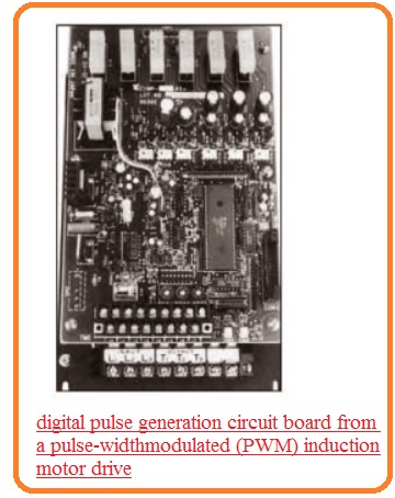
- The normal digital pulse production circuit board through a pulse width modulation induction moor can be seen here.
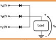
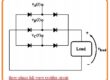
- The generation of pulses for triggering SCR, Triac and GTO is a complicated process of solid-state power controls The basic analog circuitry can be seen here the instance of single the most common category of pulse generation circuits are more common.
Relaxation Oscillator Using a PNPN Diode
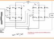
- The below figure indicates the relaxation oscillator circuitry created through the PNPN diode.
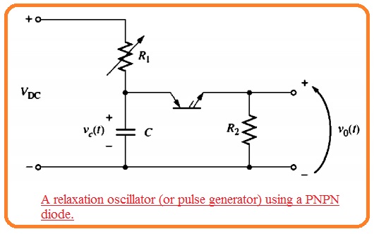
- For this circuitry creation, there should be some parameters. Those are mentioned here.
- The power supply voltage VOC should larger than the VBO for the PNPN diode.
- VDC/R1 should be less than IH for the case of PNPN diode
- Value of resistance R1 should be high than R2
- When the switch in the circuitry is closed capacitor C will get charged from the resistance R1 having a time interval T=R1C.
- The voltage at capacitor created it will become larger than the VBO and PNPN diode gets on.
- When the PNPN diode gets on the capacitor will discharge.
- The discharging will occur very fastly since R2 is less than R1 When the capacitor is gets discharged the PNPN diode will gets on as the steady-state current passing from the R1 is leser than the current IH passing from the PNPN diode.
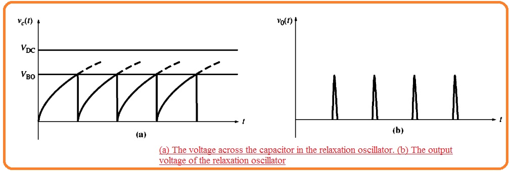
- The voltage about the capacitor and resultant output voltage and current can seen here
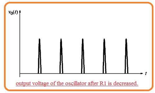
- The timing of such pulses can be varied through resistance R1 assume that resistance R1 is decreased. Then the capacitor will charge with high speed and PNPN diode will gets triggered.
- The pulses will thus close to each
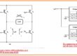
- This circuitry can be used to trigger the SCR through eliminating resistance R2 and linking the SCR gate terminal in its position.
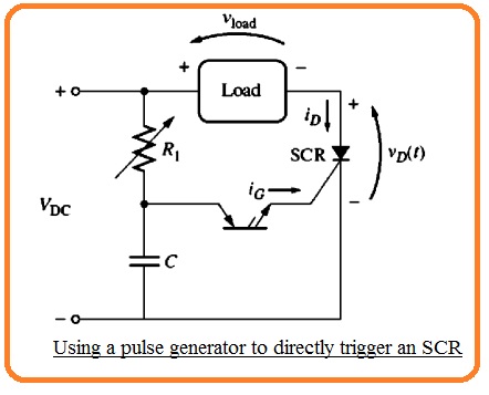
- With an alternative way, the pulse can be linked to the SCR from the transformer as can see here..
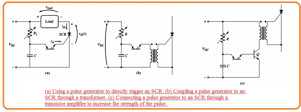
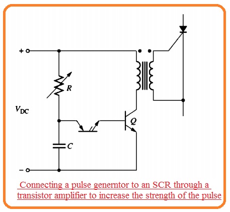
- IF a high-value gate current is required to run SCR or Triac then the pulse can become amplified through an additional transistor phase shown her.
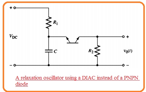
- Similar basic circuitry can be created through the use of DIAC in the position of the PNPn diode.
- It will operate above-mentioned way.
What is Pulse Synchronization
- In ac applications, it is significant that triggering pulse given at the control SCR at a similar location over every ac cycle.
- This method is generally used to synchronize the pulse circuitry to ac power line supply power to SCR.
- It can be created through the power supply to the triggering cirucitry the similar as a power supply to the SCR.
- If the triggering circuitry is given through half cycle of the ac power the RC circuitry will start to charge the starting of cycle therefore pulse will exist at fix time according to the start of the cycle
- Pulse synchronization in 3 phase circuitry and inverters is more complicated.