 Hi readers welcome to the new post. In this post, we will have a detailed look at Introduction to Cycloconverters. There are 2 main types of power supply first one is AC and second one is dc. You are well aware that only AC power can be produced and due to less cost it can be transmitted at longer distance and used to run different machines like motor and generators. In some cases the voltage and frequency get from the generation points is not has enough quality to operate the different industrial devices.
To fulfill these requirements there is use of converters and inverters to the transformation of power from one level to other that required for machines. Like these inverters, a cyclo converter is a type of converter that transforms AC power from one frequency level to another frequency level. Here we covers details of these devices and related factors. So get started with Introduction to Cycloconverters.
Introduction to Cycloconverters
- The cycloconverter is such an instrument that used to transform ac power from one frequency level to another frequency level.
- If we compare this circuitry to the rectifier inverter circuitry then we come to know that cycloconverter consists of numerous SCRs and has complicated circuitry.
- Either it has complicated circuitry but its cost is less than the rectifier inverters having high value of power ratings.
- This oduel is exist in constatn frequency and varaible freqeuncy category. The constant frequency cycloconverter is used to offers the power at different frequency levels from power source.
- The variable frequency cycloconverter are employed to offers a varaible output voltage and frequency through a constatn voltage and constant frequency power source.
- These circuits are used to run induction motors.
- The input given to the cycloconverter is 3 phase supply that compriss of 3 voltae having simiarl value and phase difference of one twenty degrees.
- The required output voltage is certain signal that is sine waveform at different frequency value.
- The cycloconverter produces required output signal through making the mixture of 3 input phase that generally fulfill the required output voltage at every time.
- Normally 2 main types of cycloconverter first one is noncirculating current cycloconverter and second one is circulating current cycloconverter.
cycloconverter Basic Concepts
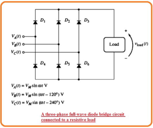
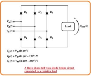
- The simple method to start discussion about this module is to observe the 3 phase full wave bridge rectifeir ciructry that has been discussed in previous tutorial.
- This circuitry can seen here.
- This circuitry consists of resistance as load. In this circuitry, the diodes parted in the 2 parts positive and negative half.
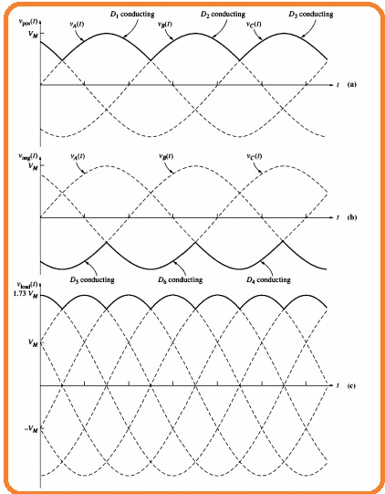
- In this positive half portion diodes having the high voltage value given it and will operate and it makes reverse-biased state for other 2 diodes.
- In case of the negative part the diodes having less voltage given to it and it will conduct and other 2 diodes will be in reverse biased condition.
- The resultant output can seen here.
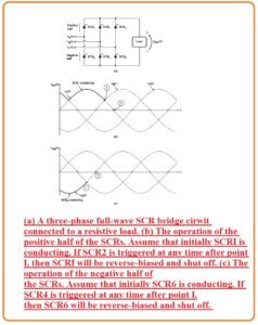
- Let us assume that 6 diodes in the bridge circuitry are removed and 6 SCRs are linked to their place.
- Now suppose that at start SCR is operating can seen in figure denoted as b.
- This SCR will retain their operation till the current decrease to IH.
- If there is no other SCR is triggerd in positve part than SCR1 will be gets off when the voltage VA is 0 changes the polairty at location no two.
- If SCR2 is get triggered at any location after point one SCR1 become reversed biased and gets off.
- The procedure through which SCR2 caused SCR1 to gets off is known as forced commutation it can be observed that forced commutation is likely only for phase angle among the location one and two.
- The SCCR is negative half operates in like way as can seen in above figure denoted as c.
- Observe that if every of the SCR is fired as commutation is certain then ouput of bridge circutry will has like value as the ouput of full wave didoe bridge refctifer
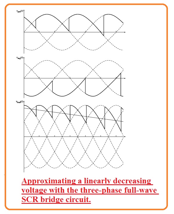
- Now observe that it is required to generate linear reducing output voltage through this circuitry can seen here.
- For generation of this output, the conducting SCR in positive half part of bridge circuitry should be gets off when value of voltage of this circuitry decreases than the required voltage level.
- It is occur through the triggering another SCR voltage over the required level
- Like this conducting SCR in negative half part of bridge circutry should be gtes off when this voltage increases over the reuired value.
- Through triggering the SCR in positive and negative half parts at accurate time it is likely to generate an output voltage that reduces in a method related to the required signal.
- it can observe from here that numerous harmonic elements exist in the resultant output voltage.
- If there is parallel combination among the 2 SCR bridges circuitryq having reverse polarity the outcome is non circulating current cyclocnverter.
Noncirculating Current Cycloconverters
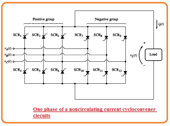
- The circuit of one phase of noncirculating current cycloconverter can be seen here.
- The complete three-phase cycloconverter comprises of 3 similar mode of this category.
- Every module comprises of 2 thee phase full wave SCR brdige circuitry one opperating current in positive direction and one operatin current in the negative direction
- The SCR in these circutry are triggered therefore to like the sine waveform having the SCRs in positive group that get triggered when current moving in positive direction and SCR in negative.
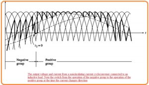
- The resultant output voltage can seen here.
- In this above circutry the noncirculating current cyclocnverter generate an ouput voltagte having large harmonic component.
- These larger harmonic restrict output frequency of the cycloconverter to parameters decrease than 1/3 of input frequency.
- With that observe that current moving should be triggered from the positive level to the negative level as the load current changes direction.
- The cycloconveter pulse control circuitry should observe this current varation with current polarity detector and switch through triggering single group of SCR triggerig second part.
- It is normally a detailed duration through variation through which positive not negative part is operating.
- This current blockage results extra harmonics in the output signal
- The large harmonic component less extreme frequencyxy and current harmonics related to noncirculating current cycloconverter join the restrict their application.
- For any normal noncirculating current cycloconverter the filter is postioned among the ouput of cyclocnveter and load to decreases output harmonics.
Circulating Current Cycloconverters
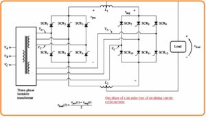
- The circuitry of circulating current cycloconverter can seen here.
- It is not like the noncirculating current cycloconverter becuse in this configurtion positive and negative parts are linked to the 2 big size inductors and load is is linked to the 2 central part of 2 inductors.
- COntrary to noncirculating current cycloconverter these 2 positive and negative parts are operating at single time and circulating current moves about the loop created through 2 parts postiive and neegative and inductors linked in series combination.
- The series inductors should has enough size in circuitry of this category to restrict the circulating current to safe level.
- The output voltage through the circulating current cycloconverter has less harmonic component than the output get from the noncirculating cycloconverter and its exreme freuency will has high value.
- It has less power factor in cause of larger series inductros therefore capacitro is generally used to cover the P.F.
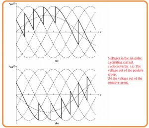
- The main cause that due to the circulating current cycloconverter has less harmonic components can seen here.
- Diagram denoted as a indicates the output voltage of the positive part and figure denoted as b indicates the output voltage of negative portion.
- The output voltagae about the cener taped inductor is mentioend here.
Vload(t)={Vpost(t)-Vneg(t)}/2
- Numerous high-frequency harmonic elements that look when the positive and negative portion are observed partly are join to these two parts.
- Since they cancel out during the subtraction and not look at the terminals of cyclocnverter.
- Certain recirculating current cycloconverter are complicated that shown in the below figure.
That all about Cycloconverters if you have any further query ask in comments. Thanks for reading have a nice day.


