 Hello, friends welcome to another interesting post. In this post, we will have a detailed look at Introduction to Switching Regulators. In previous tutorials, we discussed the 2 categories of linear regulators first is series and 2nd is a shunt that uses transistors as a control component. That operates continuously and the number of conduction changes according to the variation in the output voltage.
The switching regulator is different since the control component operates as a switch. In this post, we will have a complete look at circuit operation and some other factors of switching regulators. So let’s get started with Switching Regulators.
Introduction to Switching Regulators
- The larger value of efficiency can be obtained through the switching category of voltage regulator after that linear category provides efficiency since the transistor gets on and off and loss energy in case of on state.
- In linear regulator, the transistor remains on and dissipation of power occurs at a regular basis since the transistor operates like a variable resistance.
- It causes heat to produce and dissipate energy. In the case of the switching regulator, the transistor works at the end of the load line without during very small switching time.
- In consequence, the value of efficiency can be larger than ninety percent.
- These regulators are mostly used in such applications where efficiency is required like computers.
- A highly efficient converter reduces the large value of heat dissipation that causes the distance for the electronic element.
- Switching regulators are constructed having different values of power. The range of power lies less than one Watt for such devices that operates on battery and in some cases power range is a hundred to thousand watts in certain applications.
- These requirements for applications find the specific structure but every switching regulator need feedback for regulating the on and off time for a switch
- 3 main arrangements of switching regulators are given first one is step down, 2nd is step up and the third one is inverting.
- In certain circumstances like laptop computer, all these categories are sued.
Step-Down Arrangement
- In this type of arrangement, the output voltage is less than the input voltage.
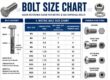
- The main idea for a step-down category is can be seen in the below figure.
- The main control component is a high-speed switch that opens and close very fastly to the control circuitry which detect the output and it regulates the at a given time and off time to retain the required output.
- When the switch is in a closed state the diode is off and the magnetic field of inductors generates stored energy.
- When the switch is open the magnetic files diminish retaining an almost constant current at the output.
- The path for the load current is offered by the forward-biased diode.
- The capacitor causes the dc to become smooth at a constant level.
- Observe that the circuitry comprises the switching element. The switch gets on and off the input voltage at a very fast speed and with a duty cycle which relies on the regulator load needed.
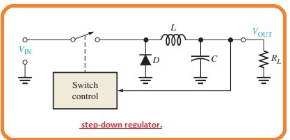
- The below figure indicates a simple category of a step-down switching regulator with the use of D-MOSFET switching transistor.
- The MOSFET transistor do switching with a higher speed than the BJT and has enhanced its features in previous years.
- The pulsed current cause by the transistor is converted in a smooth form with eh LC filter.
- The inductor causes the current to have a constant value and the capacitor cause to voltage has the same value.
- In ideal, these elements do not lose power but in some loss causes due to some factors.
- To minimize these factors use a large number of inductors and capacitors the switching frequency is chosen to be very high-value that the utility frequency value close to twenty-kilo hertz.
- The disadvantage to large frequency is caused by electric noise. Switching power sends harmonic frequency noise to close existing circuitry. That provides protection and frequency need electromagnetic interference.
- As the switching element losses, many parts of its time in the cutoff or saturation process the power dissipation in the control component is generally less.
Step Down Arrangement
- This type of configuration is called buck converter and its output is less than the input voltage.
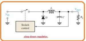
- The basic circuit configuration is shown in the below figure.
- The main component of this circuitry is a high-speed switch that closes or opens very fastly to the control circuitry which detects the output and it regulates the on time and off time to provides the required output.
- When the switch gets closed the diode is in off state and the magnetic field of the inductor generates high power energy.
- When the switch is getting open the magnetic field diminishes and keeps the constant value of current at the load.
- The path for the load current is given by the forward-biased diode.
- In the below figure, you can see the circuitry that comprises of switching components.
- Switch on and off the input voltage at fast rate and with the duty cycle which relies on the load requirement of the load.
- The below diagram indicates the basic step down switching regulator that using the D MOSFET switching transistor.
- The MOSFET can do switching processes with high speed than BJT and provides better results than in previous years.
- Due to this feature, it mostly preferred as the switching component offers the off-state voltage is not very large.
- In most electronic instruments there is trade-offs for engineers in selecting a switching component.
- In the respective design the breakdown voltage, on-state resistance and switching time take into consideration.
- In some applications, thyristors are used.
- The pulsed current from the transistor is converted in a smooth form with the LC filter.
- The inductor retains the value of the current constant and the capacitor causes the voltage to remain constant.
- In the ideal case, these elements not lose power but in real cases, loss occurs to numerous parameters.
- To decrease the usage of large inductors and capacitors the range of switching frequency is retained greater than twenty-kilo hertz.
Read also
- Comprehensive Guide to PCB Voltage Regulators: Types and Applications
- Introduction to 7805 Voltage Regulator, Pinout, Working, Applications
- Introduction to Shunt Regulators
- Integrated Circuit Voltage Regulators
That is a detailed post about Switching Regulators if you have any further queries ask in the comments. Thanks for reading. Have a nice day.