 Hello, readers welcome to another interesting post. In this post, we will have a detailed look at Introduction to Linear Shunt Regulators. In the previous tutorial, we discussed the linear voltage regulator with the details. We discussed that the control component in the series regulator was a series pass transistor.
While in the shunt regulator is a transistor in a parallel configuration with load is a control component. In this post, we will have a detailed look at its circuit operation and some other related factors. So let’s get started with Introduction to Linear Shunt Regulators.
Introduction to Linear Shunt Regulators
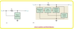
- The simple configuration of this category of the regulator can be seen in the below figure denoted as a’ and component of the circuitry are shown in block diagram denoted as b’.
- In this shunt regulator configuration, the control component is a transistor in parallel combination with the load can be seen in the below figure.
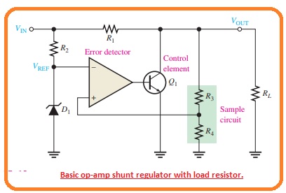
- The resistance R1 is linked to the series combination with the load. The working of the circuitry is like to the series regulator with the difference is that regulation is obtained through regulating the current passing in the parallel transistor Q1.
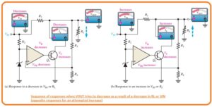
- When the value of output voltages goes to decrement due to variation in the input voltage or load current generated by the variation in the load resistance can be seen in the below figure.
- The decrement is observed by the resistances R3 and R4 and given to the non-inverting input.
- The resultant difference voltage decreases the operational amplifier output to decrement that decreasing its collector current value and rises the collector voltage.
- So the real decrement in voltage is overcome due to this increment and retains the value of output almost constant.
- The reverse process exists when the output goes to increment as can be seen in the above figure.
- With the value of current IL and VOut constant, the variation in the input voltage generates a variation in the shunt current.
ΔIS=VIN/R1
- the constant value of Vin and Vout variation in the load current causes a reverse variation in the shunt current. If there is an increment in current IL and decrement in Is.
ΔIS = -ΔIL
- The shunt regulator is less effective than the series category but provides protection from short circuit.
- If the output is short-circuited the load current is restricted with the series resistance to the extreme point as given.
IL(max)=VIN/R1
That is all about the Linear Shunt Regulators I tried my level best to make it simple for you if you have any further query ask in the comments. Thanks for reading. have a nice day.


